1
QUICK REFERENCE OF ALARMS AND FAULTS
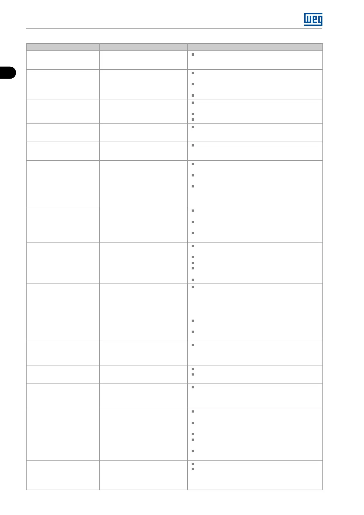
Fault / Alarm Description Possible Causes
F081
End of User’s Memory
Fault of end of memory to save user’s
parameter table.
Attempt to save (P204 = 9) more than 32 parameters
(with values different from the factory default) on the User
parameter table.
F082
Fault in Data Transfer (MMF)
Fault in data transfer using MMF
accessory.
Attempt to download data from the flash memory module
to the inverter with the inverter energized.
Attempt to download a SoftPLC application incompatible
with the destination inverter.
Problems saving data downloaded to the inverter.
F084
Auto-diagnosis Fault
Fault related to the automatic
identification algorithm of the inverter
hardware.
Poor contact in the connection between the main control
and the power pack.
Hardware not compatible with the firmware version.
Defect on the internal circuits of the inverter.
A090
External Alarm
External alarm via DIx (option “no
external alarm” in P263 to P270).
Wiring on DI1 to DI8 inputs are open or have poor contact.
F091
External Fault
External fault via DIx (“no external fault”
in P263 to P270).
Wiring on DI1 to DI8 inputs are open or have poor contact.
A128
Telegram Reception Timeout
It indicates that the device stopped
receiving valid telegrams for a period
longer than the setting in P314.
The time counting starts as soon as it
receives the first valid telegram, with
correct address and error-checking
field.
Check network installation, broken cable or fault/poor
contact on the connections with the network, grounding.
Ensure the master always sends telegrams to the
equipment in a time shorter than the setting in P314.
Disable this function in P314.
A133
No Power Supply on the CAN
Interface
It indicates that the CAN interface has
no power supply between pins 25 and
29 of the connector.
Measure if there is voltage within the allowed range between
pins 25 and 29 of the CAN interface connector.
Check if the power supply cables are not misconnected or
inverted.
Check for contact problems on the cable or connector of
the CAN interface.
A134
Bus Off
Bus off error detected on the CAN
interface.
Check for short circuit on the CAN circuit transmission
cable.
Check if the cables are not misconnected or inverted.
Check if all the network devices use the same baud rate.
Check if the termination resistors with the right specification
were installed only at the end of the main bus.
Check if the CAN network was properly installed.
A135
Node Guarding/ Heartbeat
CANopen communication error control
detected communication error using
the guarding mechanism.
Check the times set on the master and on the slave for
message exchange. In order to prevent problems due to
transmission delays and time counting, it is recommended
that the values set for error detection by the slave be
multiples of the times set for message exchange on the
master.
Check if the master is sending the guarding telegrams in
the time set.
Check problems in the communication that may cause
missing telegrams or transmission delays.
A136
Idle Master
Alarm indicates that the DeviceNet
network master is in Idle mode.
Set the switch that controls the master operation of the
master for Run or the corresponding bit on the configuration
word of the master software. If further information is
needed, refer to the documentation of the master used.
A137
DeviceNet Connection Timeout
Alarm that indicates that one or more
DeviceNet connections timed out.
Check the network master status.
Check network installation, broken cable or fault/poor
contact on the connections with the network.
A138
Profibus DP Interface in Clear
Mode
It indicates that the inverter received
the command from the Profibus DP
network master to go into clear mode.
Check the network master status, ensuring it is in the run
mode.
A139
Offline Profibus DP Interface
It indicates interruption in the
communication between the Profibus
DP network master and the inverter.
The Profibus DP communication
interface went into offline status.
Check if the network master is correctly configured and
operating properly.
Check for short-circuit or poor contact on the
communication cables.
Check if the cables are not misconnected or inverted.
Check if the termination resistors with the right value were
installed only at the end of the main bus.
Check the network installation in general - cabling,
grounding.
A140
Profibus DP Module Access
Error
It indicates error in the access to the
Profibus DP communication module
data.
Check if the Profibus DP module is correctly fitted.
Hardware errors due to improper handling or installation
of the accessory, for instance, may cause this error. If
possible, carry out tests by replacing the communication
accessory.
1-2 | Micro Mini Drives