8
MOTOR CONTROL
U
d
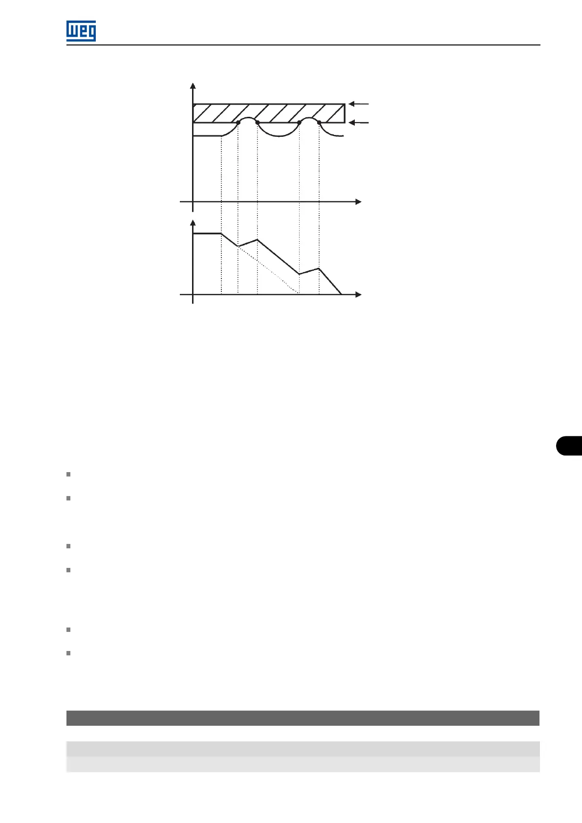
P151
Output
frequency
Time
Time
U
d
rated
DC Link
regulation
F022 - overvoltage
DC Link voltage (P004)
Figure 8.5: Example graph of the DC Link voltage limitation - Accelerate Ramp (P150 = 0 or 1)
8.1.2.2 Output Current
Like in the DC Link voltage regulation, the output current regulation also has two operating modes: ”Ramp Holding”
(P150 = 2 or 3) and ”Decelerate Ramp” (P150 = 0 or 1). Both actuate limiting the torque and power delivered to the
motor, so as to prevent the shutting down of the inverter by overcurrent (F070). This situation often occurs when a
load with high moment of inertia is accelerated or when short acceleration time is programmed.
8.1.2.2.1 Output Current Limitation by “Ramp Hold” (P150 = 2 or 3)
It prevents the motor from collapsing during torque overload in the acceleration or deceleration.
Actuation: if the motor current exceeds the value set in P135 during acceleration or deceleration, the frequency
will not be incremented (acceleration) or decremented (deceleration). When the motor current reaches a value
below P135 the motor accelerates or decelerates again. Refer to Figure 8.6 on page 8-8.
It has a faster action than the ”Decelerate Ramp” mode.
It acts in the motorization and regeneration modes.
8.1.2.2.2 Current Limitation Type “Decelerate Ramp” (P150 = 0 or 1)
It prevents the motor from collapsing during torque overload in the acceleration or constant frequency.
Actuation: if the motor current exceeds the value set in P135, a null value is forced for the frequency ramp input
forcing the motor deceleration. When the motor current reaches a value below P135 the motor accelerates again.
Refer to Figure 8.6 on page 8-8.
P135 - Maximum Output Current
Range: 0.0 to 40.0 A
Properties: V/f
Description:
Micro Mini Drives | 8-7