14
APPLICATIONS
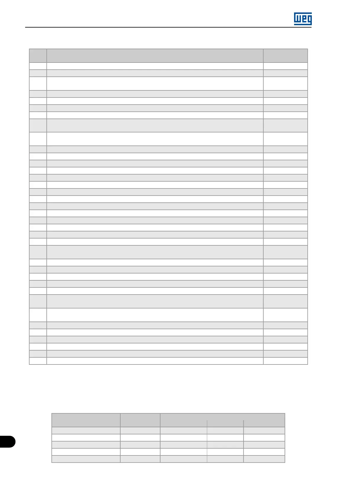
Table 14.2: Programming sequence of the PID controller application
Seq. Action / Result
Indication on the
Display
1 It selects the PID controller application in the SoftPLC function of the inverter P903 = 1
2 It enables the execution of the PID controller application P901 = 1
3
It selects the PID controller control action, thus enabling its operation and uploading, at this moment
the application default setting (which is indicated below) to the frequency inverter. 1 = Direct
P928 = 1
4 Acceleration time in seconds P100 = 2.5 s
5 Deceleration time in seconds P101 = 2.5 s
6 Minimum motor speed in rpm P133 = 40.0 Hz
7 Maximum motor speed in rpm P134 = 60.0 Hz
8
It selects the parameter of the HMI main display to show the value of the PID controller process variable
This setting is optional
P205 = 916
9
It selects the HMI bar graph parameter to show the present motor speed.
This setting is optional
P207 = 002
10 Full scale of the Speed Reference P208 = 600
11 Engineering unit of the Speed Reference P209 = 3
12 Speed Reference indication form P210 = 1
13 Full scale of the HMI bar graph P213 = 600
14 LOC/REM Source Selection. 0 = Always Local P220 = 0
15 Selection of the Reference in Local mode. 12 = SoftPLC P221 = 12
16 Selection of the Run/Stop Command in Local mode. 1 = DIx P224 = 1
17 AI1 Signal Function. 17 = Process Variable (PV) P231 = 17
18 AI1 Gain P232 = 1.000
19 AI1 Signal. 1 = 4 to 20 mA P233 = 1
20 Offset AI1 P234 = 0.00 %
21 Filter AI1 P235 = 0.25 s
22 Digital input DI1 is used for the motor run or stop command. 1 = run/stop P263 = 1
23 Digital input DI2 is used to set the PID to Automatic or Manual. 50 = PID Man / Auto P264 = 50
24
SoftPLC Engineering Unit. 0 = none. The sensor of the process variable is in bar, and this
variable is not available on the inverter
P510 = 0
25 Indication form of the SoftPLC engineering unit. 2 = wx.yz P511 = 2
26 It selects the PID controller operation mode. 2 = manual/automatic via DI2 P929 = 2
27 It selects the automatic setting mode of the control setpoint. 0 = P911 inactive and P918 inactive P930 = 0
28 The PID controller Setpoint will be set via HMI. 0 = via HMI P920 = 0
29 The PID Process Variable will be read via analog input AI1. 1 = via AI1 P921 = 1
30
The range of the sensor connected to analog input AI1 is 0 to 4.0 bar. Program this parameter for
the minimum sensor value, which is the maximum of the analog input 4 mA
P922 = 0.00
31
The range of the sensor connected to analog input AI1 is 0 to 4.0 bar. Program this parameter for
the maximum sensor value, which is the maximum of the analog input 20 mA
P923 = 4.00
32 Setting of the control Setpoint via HMI P911 = 2.00
33 Control Setpoint Filter P935 = 0.150 s
34 PID controller Sampling Period P934 = 0.100 s
35 Proportional Gain of the PID controller P931 = 1.00
36 Integral Gain of the PID controller P932 = 5.00
37 Derivative Gain of the PID controller P933 = 0.00
Parameters P931, P932, P933 and P934 must be set according to the response of the process to be controlled.
See below suggestions for initial values of sampling time and gain setting for the PID controller according to the
process to be controlled.
Table 14.3: Suggestions for the PID controller gain settings
Gains
Quantity
Sampling Time
P934 Proportional P931 Integral P932 Derivative P933
Pressure in pneumatic system 0.10 s 1.00 5.00 0.00
Flow in pneumatic system 0.10 s 1,00 5.00 0.00
Pressure in hydraulic system 0,10 s 1.00 5.00 0.00
Flow in hydraulic system 0.10 s 1,00 5.00 0.00
Temperature 0.50 s 2.00 0.50 0.10
14-4 | Micro Mini Drives
 Loading...


