14
APPLICATIONS
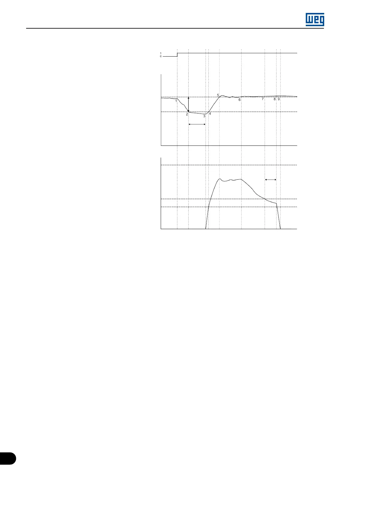
COMANDS - DIGITAL INPUTS
DI1 - run/stop
PROCESS VARIABLE
P911 - control setpoint
MOTOR SPEED (Hz)
P134 - maximum speed reference
P938 - motor speed to activate the sleep mode
P133 - minimum speed reference
P936 - process variable deviation to wake up
P937 - time to wake up
P939 - time to activate
the sleep mode
Figure 14.4: Operation of the PID controller with the sleep mode enabled
1. The Run/Stop command via digital input DI1 enables the starting of the motor. As the wake up condition was
not detected, it remains in sleep mode, and the motor remains stopped.
2. The process variable starts to decrease and becomes smaller than the deviation of the process variable
programmed to wake up (P936); at this moment, the time count to wake up (P937) begins.
3. The process variable remains smaller than the process variable deviation to wake up (P936), and the time to
wake up (P937) elapses; at this moment, the command to start the motor and control the system with its
speed variation is executed.
4. The inverter accelerates the motor up to the minimum speed (P133). After that, the PID controller is enabled
and starts controlling the motor speed.
5. Then it is possible to control the process variable so that it reaches the control setpoint required by the user.
To that end, the PID controller output is incremented, making the motor speed increase until reaching the
control stabilization.
6. The value of the process variable remains above the required control setpoint due to a decrease in demand,
and the motor speed starts slowing down.
7. The value of the motor speed falls below the value to sleep (P938); the time count to activate the sleep mode
(P939) begins.
8. The motor speed remains below the value to sleep (P938), and the time to activate the sleep mode (P939)
elapses; at this moment, the command to switch off the motor is executed.
9. The motor is decelerated down to 0 Hz and remains stopped; at this moment the PID controller goes into the
sleep mode.
14-16 | Micro Mini Drives