8
MOTOR CONTROL
Slip Compensation during the Regeneration (Bit 0 )
The regeneration is an operating mode of the inverter which occurs when the power flux goes from the motor to
the inverter. The bit 0 of P397 (set in 0) allows the slip compensation to be turned off in this situation. This option
is particularly useful when the compensation during the motor deceleration is necessary.
Dead Time Compensation (Bit 1)
The dead time is a time interval introduced in the PWM necessary for the commutation of the power inverter
bridge. On the other hand, the dead time generates distortions on the voltage applied to the motor, which can
cause torque reduction at low speeds and current oscillation in motors above 5 HP running with no load. Thus,
the dead time compensation measures the voltage pulse width in the output and compensates this distortion
introduced by the dead time. This parameter must be kept always in 1 (On). Only in special maintenance cases
the value 0 (Off) can be used.
Output Current Stabilization (Bit 2)
High-performance motors with power above 5 HP are marginally stable when driven by frequency inverters and
at operation with no load. Therefore, in this situation a resonance may occur in the output current which may
reach the overcurrent level F070. Bit 2 of P397 (set to 1) activates an algorithm for regulation of the output current
in closed loop which neutralizes the oscillations of resonant output current.
Reduction of P297 at high temperature (Bit 3)
Bit 3 of P397 controls the action to reduce the switching frequency together with the overtemperature protection
according to Table 11.1 on page 11-4. If the temperature exceeds the value of A050, the switching frequency is
reduced proportionally down to its minimum when the temperature reaches the level of F051.
✓
NOTE!
Both the function related to P219 and the function controlled by P397 (bit 3) act by reducing the
switching frequency. As the function related to P219 is intended to improve the reading of the inverter
current, that function has priority of action over the function controlled by P397 (bit 3).
!
WARNING!
The default setting of P397 meets most application needs of the inverter. Therefore, avoid modifying
its content without knowing the related consequences. If you are not sure, contact WEG Technical
Assistance before changing P397.
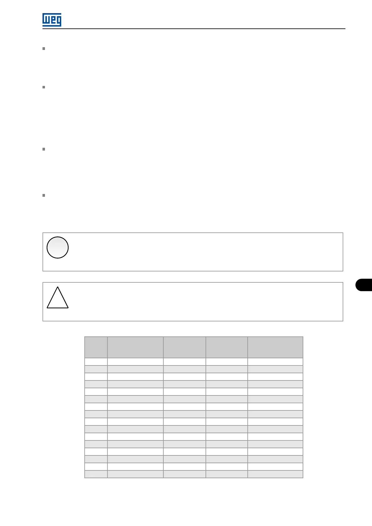
Table 8.5: Options available to configure the control (P397)
P397
Bit 3
Reduction of P297 in
A050
Bit 2
Output Current
Stabilization
Bit 1
Dead Time
Compensation
Bit 0
Slip Compensation
During Regeneration
0000h Disabled Disabled Disabled Disabled
0001h Disabled Disabled Disabled Enabled
0002h Disabled Disabled Enabled Disabled
0003h Disabled Disabled Enabled Enabled
0004h Disabled Enabled Disabled Disabled
0005h Disabled Enabled Disabled Enabled
0006h Disabled Enabled Enabled Disabled
0007h Disabled Enabled Enabled Enabled
0008h Enabled Disabled Disabled Disabled
0009h Enabled Disabled Disabled Enabled
000Ah Enabled Disabled Enabled Disabled
000Bh Enabled Disabled Enabled Enabled
000Ch Enabled Enabled Disabled Disabled
000Dh Enabled Enabled Disabled Enabled
000Eh Enabled Enabled Enabled Disabled
000Fh Enabled Enabled Enabled Enabled
Micro Mini Drives | 8-17