1
WEILER E1250
1-6
General Information
1
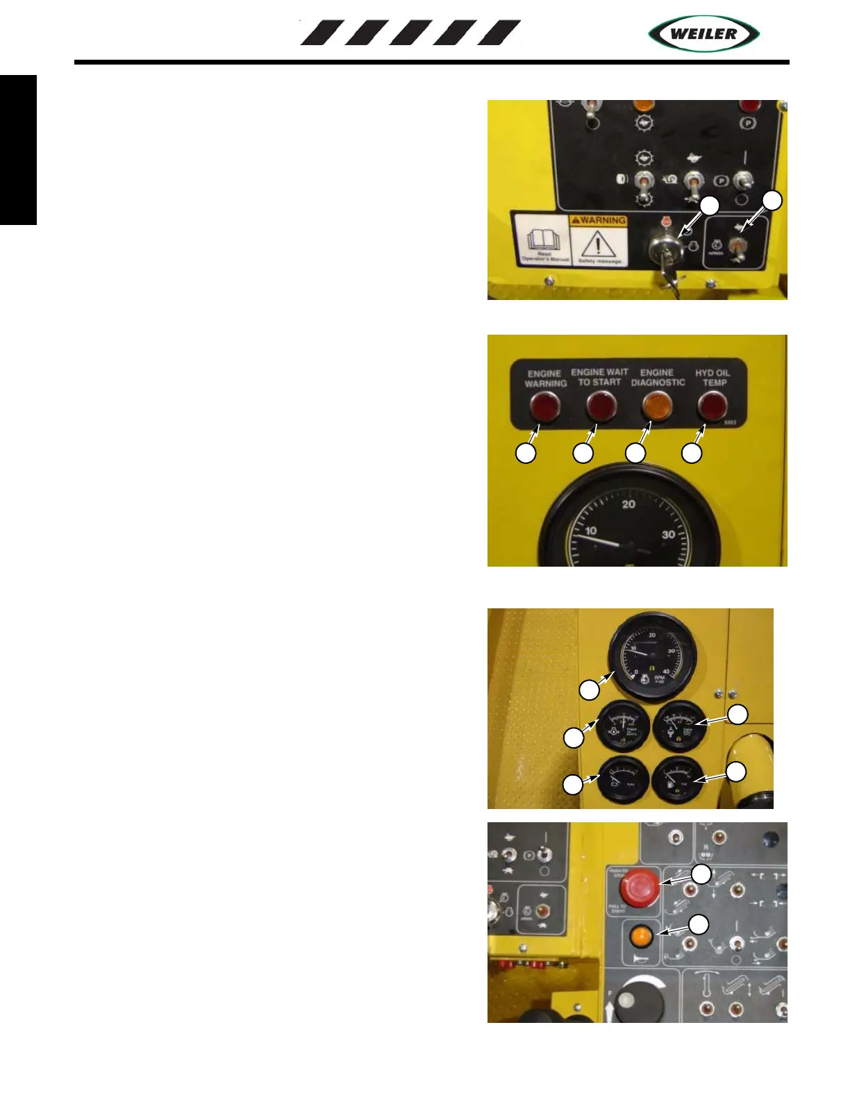
OPERATOR STATION - ENGINE CONTROLS
1. Ignition Switch (1) - The ignition switch is a key operated,
three position rotary switch that controls engine starting,
stopping, and accessories. Vertical position is the OFF position.
The next position clockwise is ON or running position. The
farthest most clockwise position is CRANKING position.
2. Engine Speed Switch (2) - Adjusts engine RPM, up for higher
engine speed, down for lower engine speed.
3. Engine Warning Light (3) - Red light illuminates when engine
control module detects a fault that may damge the engine,
operator should shut down the engine when appropriate.
4. Engine Wait to Start (4) - Red light illuminates until glow
plugs are fully warmed up.
5. Engine Diagnostic (5) - Amber light illuminates or flashes to
warn operator when the engine control module detects an engine
problem which needs to be corrected.
6. Hydraulic Oil Temperature (6) - Red light illuminates to warn
operator that the hydraulic reservoir temperature is above 210
degrees F.
7. Engine Tachometer
8. Engine Oil Pressure
9. Engine Water Temperature
10. Volt Meter
11. Fuel Gauge
12. Stop Switch- Push Stop switch to shut down engine, switch
must be pulled out to run the engine.
13. Horn- Press to operate horn.
Key Switch and throttle
1
2