CONTROL
PANELS
MAIN
PANEL
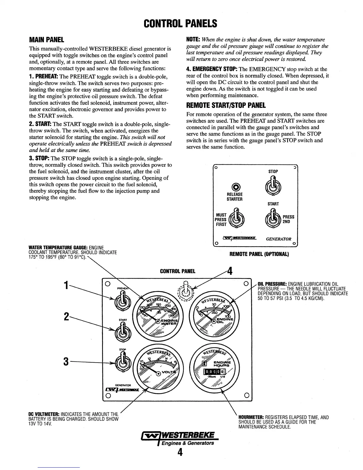
This manually-controlled WESTERBEKE diesel generator is
equipped with toggle switches
on
the engine's control panel
and, optionally, at a remote panel. All three switches are
momentary contact type and serve the following functions:
1.
PREHEAT:
The
PREHEAT toggle switch is a double-pole,
single-throw switch.
The
switch serves two purposes: pre-
heating the engine for easy starting and defeating
or
bypass-
ing the engine's protective oil pressure switch. The defeat
function activates the fuel solenoid, instrument power,
alter-
nator excitation, electronic governor and provides power to
the START switch.
2.
START:
The
START toggle switch is a double-pole, single-
throw switch.
The
switch, when activated, energizes the
starter solenoid for starting the engine.
This
switch will not
operate electrically unless the PREHEAT switch
is
depressed
and held at the same
time.
3.
STOP:
The
STOP toggle switch is a single-pole, single-
throw, normally closed switch. This switch provides power
to
the fuel solenoid, and the instrument cluster, after the oil
pressure
switqh has closed upon engine starting. Opening
of
this switch opens the power circuit to the fuel solenoid,
thereby stopping the fuel flow
to
the injection pump and
stopping the engine.
WATER
TEMPERATURE
GAUGE:
ENGINE
COOLANT.
TEMPERATURE.
SHOULD
INDICATE
1W.T0·1-95°F
(80°
TO
91°C).
NOTE:
When
the engine
is
shiP
down,
the
water temperature
gauge and the oil pressure
gauge will continue
to
register
the
last temperature and oil pressure readings
displayed.
They
will return
to
zero once electrical power is
restored.
4.
EMERGENCY
STOP:
The EMERGENCY stop switch at the
rear
of
the control
box
is normally closed. When depressed, it
will open the
DC
circuit to the control panel and shut the
engine down.
As the switch is not toggled it can be used
when performing maintenance.
REMOTE
START/STOP
PANEL
For remote operation
of
the generator system, the same three
switches are used.
The
PREHEAT and START switches are
connected in parallel with the gauge panel's switches and
serve the same functions as in the gauge panel. The
STOP
switch is in series with the gauge panel's STOP switch and
serves the same function.
0
@
RELEASE
STARTER
MUST~
PRESS.
FIRST
t'W'JMi'
.......
0
STOP
~
START
A
PRESS
~2ND
GENERAToR
o·
REMOTE
PANEL
(OPTIONAL)
CONTROL
PANEL
1
2
DC
VOLTMETER:
INDICATES
THE
AMOUNT
THE.
BATIERY
IS
BEING
CHARGED.
SHOULD
SHOW
13VTO
14V.
Engines & Generators
4
0
mL
PRESSURE:
ENGINE
LUBRICATION
OIL
PRESSURE-
THE
NEEDLE
WILL
FLUCTUATE
DEPENDING
ON
LOAD,
BUT
SHOULD
INDICATE
50
TO
57
PSI
(3.5
TO
4.5
KG/CM).
.
HOURMETER:
REGISTERS
ELAPSED
TIME,
AND
SHOULD
BE
USED
AS
A
GUIDE
FOR
THE
MAINTENANCE
SCHEDULE.