SHORE
POWER
TRANSFER
SWITCH
SHORE
POWER
CONNECTIONS
(60
HERTZ)
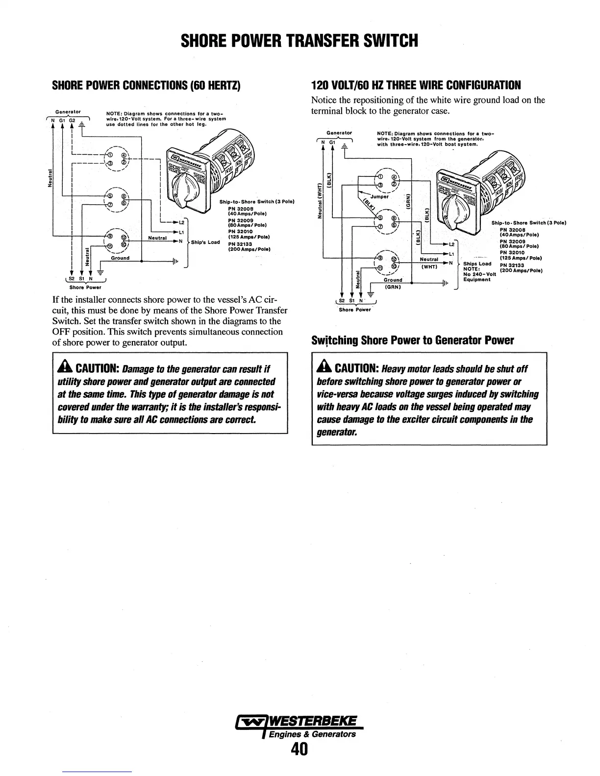
Generator
~
NOTE:
Diagram
shows
connections
for
a
two-
wire.
120•
Volt
system.
For a
three-
wire
system
use
dotted
lines
for
the
other
hot
leg.
t t
I
L------,
I
f
/,--
...
,
L-----f-(j)
~~
r-----t~
fZSi-
1 ,
__
,./
I
I
I
Ship·
to•
Shore
Switch
(3
Pole)
PN
32008
(40AmpstPole)
PN
32009
(80Amps/
Pole)
PN
32010
(125
Amps/
Pole)
PN
32133
(200Amp&/Pole)
If
the installer connects shore power to the vessel's AC cir-
cuit, this must
be
done by means
of
the Shore Power Transfer
Switch. Set the transfer switch shown in the diagrams to the
OFF
position. This switch prevents simultaneous connection
of
shore power to generator output.
A
CAUTION:
Damage
to
the
generator
can
result
if
utility
shore
power
and
generator
output
are
connected
at
the
same
time.
This
type
of
generator
damage
is
not
covered
under
the
wa"anty;
it
is
the
installer's
responsi-
bility
to
make
sure
all
AC
connections
are
co"ect.
120
VOLT/60HZ
THREE
WIRE
CONFIGURATION
Notice the repositioning
of
the white wire ground load on the
terminal block to the generator case.
Generator
NOT-E!
Diagram
shows
connections
for
a
two-
~
wire.
120·Volt
system
from
the
generator.
J
;•
r.=.-t--4-w®lth
three-wire,120-Volt
bo-at
·system.
~
~
.
z
Ship-to-
Sttore
Switch
(3
Pole)
PN
32008
(40Amps/Pole)
/--
......
,
L1
PN
32010
'----+--+--+-®
1 ·
-----
(125Amps/Pole)
1.2}
ia'1,~:~~Pole)
I
::8---l----"=c::;_
... N .
Ships
Load
PN
32133
;;~-
.,/
~~~~~-Volt
(200Amps/Pole)
j
7round
It•
Equipment
z IGRN)
-
-~
Shore PoWer
Sw'tching
Shore
Power
to
Generator
Power
A
CAUTION:
Heavy
motor
leads
should
be
shut
off
before
switching
shore
power
to
generator
power
or
vice-versa
because
voltage
surges
induced
by
switching
with
heavy
AC
loads
on
the
vessel
being
operated
may
cause
damage
to
the
exciter
circuit
components
in
the
generator.
Engines & Generators
40