DC
ELECTRICAL
SYSTEM
ENGINE
12-VOLT
DC
CONTROL
CIRCUIT
The
engine
has
a
12
volt
DC
electrical control circuit that
is
shown
on
the
wiring
diagrams
that
follow.
Refer
to
these dia-
grams
when
troubleshooting or when servicing
the
DC
elec-
trical
system
on
the
engine.
A
CAUTION:
lb
avoid
damage
to
the
battery
charging
circuit,
never
shut
off
the
engine
battery
switch
while
the
eng/nels
running.
Shut
off
the
engine
battery
switch,
howevtH,
to
avoid
electrical
shorts
when
working
on
the
engine's
electrical
circuit.
Battery
Specification
The
minimum
recommended capacity of
the
battery
used
in
the
engine's 12-volt
DC
control circuit is400-600Cold
Cranking
Amps
(CCA).
Battery
Care
Review
the
manufacturer's recommendations
and
then estab-
lish a systematic maintenance schedule
for
your
engine's
starting
batteries,
and
house
batteries.
D Monitor your voltmeter
for
proper charging during engine
operation.
D Check the electrolyte level
and
specific
gravity
with a
hydrometer.
D
Use
only
distilled water
to
bring electrolytes
to
a proper
level.
D
Make
certain that
battery
cable connections
are
clean
and
tight
to
the
battery
posts
(and to your engine).
D
Keep
your
batteries clean
and
free of
corrosion.
A
WARNING:
Sulfuric
acid
In
lead
batteries
can
cause
severe
bums
on
skin
and
damage
clothing.
Wear
protective
gear.
GLOW
PLUGS
The
glow
plug
is
a
small
heater installed
in
each
pre-combus-
tion
chamber.
They
run
off the engine starting
battery
and
become
red hot
when
activated.
The
glow
plugs
are
wired through
the
preheat
solenoid.
When
PREHEAT
is
pressed
at
the
control
panel
this
solenoid
should "click"
on
and
the
glow
plug
should
begin
to
get
hot.
Glow
plugs
can
be
checked
by
unscrewing
and
holding
them
against a
good
ground
(engine block)
and
turning
them
on.
The
tip
should
glow
red
hot.
You
can
also
use
an
ammeter
to
test the power drain
(8
to
9
amps
per
plug),
or
an
ohmmeter
to
test resistance (1.1
to
1.2
ohms).
A
WARNING:
These
glow
plugs
will
become
very
hot
·
'to
the
touch.
Be
careful
not
to
burn
your
fingers
when
testing
the
plugs.
Re-install the
plugs
in
the
engine
and
test
them
again.
The
plugs should get
very
hot
(at
the
terminal
end)
within
20
to
25
seconds.
If
the
plugs
don't heat
up
quickly,
check
for
a
short circuit.
When
reinstalling
the
glow
plugs,
use
anti-seize
compound
on
the
threads.
A
CAUTION:
Do
not
keep
glow
plug
on
for
more
than
30
seconds.
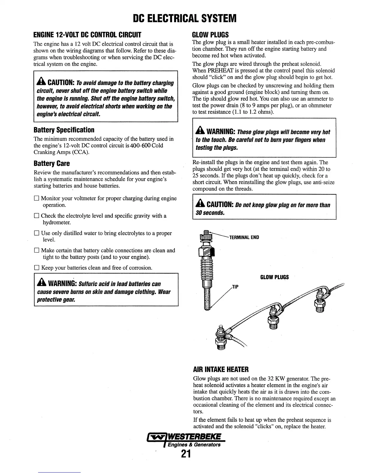
TERMINAL
END
GLOW
PLUGS
AIR
INTAKE
HEATER
Glow
plugs are
not
used
on
the
32
KW
generator.
The
pre-
heat solenoid
activates
a heater element
in
the
engine's
air
intake that
quickly
heats
the
air
as
it
is
drawn
into
the
com-
bustion
chamber.
There
is
no
maintenance
required
except
an
occasional cleaning of
the
element
and
its
electrical
connec-
tors.
If
the
element
fails
to
heat
up
when
the
preheat
sequence
is
activated
and
the
solenoid "clicks" on, replace
the
heater.
I
"fttiV'lWESTERBEICE
l Engines &
Generators
21