FUEL
SYSTEM
BLEEDING
(PRIMING)
THE
FUEL
SYSTEM/20.0
KW
AND25.0KW
There
is
one bleed point
in
the
on-engine
fuel
system
to
open
for
the removal
of
air.
On
the
20.0
KW
and
25
KW
this bleed
screw
is
located on the housing for the spin-on fuel filter
mounted on the engine. This screw should
be
opened one or
two
turns
to
remove
air
from
the upper
housing
area
of
the
fuel
filter.
Energizing
the
preheat switch
for
10-20
seconds or
by
using the palm of your
hand
to
slowly
depress
and
release
the.pJimer pump on the
top
of the filter
housing
either
method
will
force air out through the bleed
point.
Once all
air
is
expelled, tighten the bleed screw. Depress
the
preheat
switch
10-20 seconds
or
slowly pumping
the
primer
on
the
fuel
filter
housing
to
force
any air
in
the
system
between
the
filter housing and the injection pump out of
the
system and
back
to
the
fuel
tank through the return.
NOTE:
When
using the preheat function
to
bleed air
from
the
filter assembly keep
in
mind that the preheat elements (glow
plugs)
are
being
energized.
Take
care not
to
overheat
them.
BLEEDING
(PRIMING)
THE
FUEL
SYSTEM/32.0
KW
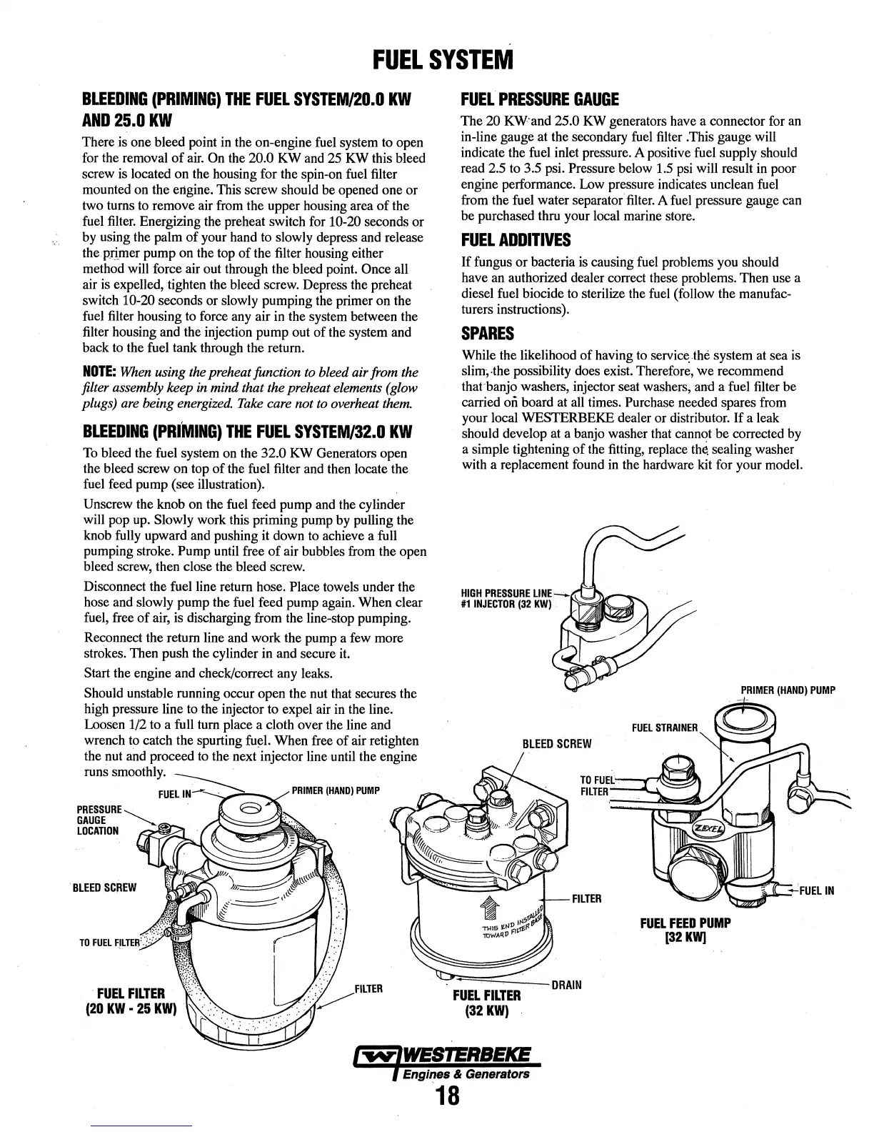
To
bleed the
fuel
system
on
the 32.0
KW
Generators open
the bleed screw on
top
of the
fuel
filter
and
then
locate the
fuel
feed
pump (see illustration).
Unscrew the knob
on
the
fuel
feed pump
and
the
cylinder
will
pop
up.
Slowly work this priming pump
by
pulling the
knob
fully
upward
and
pushing it down
to
achieve a full
pumping stroke.
Pump until
free
of air bubbles
from
the open
bleed
screw,
then close
the
bleed
screw.
Disconnect the
fuel
line return hose. Place towels under the
hose
and
slowly pump
the
fuel
feed pump
again.
When clear
fuel,
free
of
air,
is discharging from the line-stop pumping.
Reconnect the return line
and
work the pump a
few
more
strokes. Then push the cylinder in
and
secure
it.
Start the engine
and
check/correct
any
leaks.
Should unstable running occur open the
nut
that secures the
high pressure line
to
the injector
to
expel air
in
the
line.
Loosen
1!2
to
a full
turn
place a cloth over
the
line and
wrench to catch the spurting
fu~l.
When
free
of air retighten
the nut
and
proceed
to
the
next
injector line until the engine
runs smoothly.
FUEL
PRESSURE......__
GAUGE
..........._
LOCATION
.......
..,.
_....,
TO
FUEL
·
FUEL
FILTER
(20
KW
~
25
KW)
FUEL
PRESSURE
GAUGE
The
20
KW:and
25.0
KW
generators
have
a connector for
an
in-line gauge at the secondary
fuel
filter .This gauge will
indicate the fuel inlet pressure. A positive fuel supply should
read 2.5
to
3.5
psi.
Pressure below
1.5
psi
will result
in
poor
engine performance.
Low
pressure indicates unclean
fuel
from
the
fuel
water separator·
filter.
A
fuel
pressure gauge
can
be purchased thru
your
local marine store.
FUEL
ADDITIVES
If
fungus or bacteria
is
causing
fuel
problems
you
should
have
an
authorized dealer correct
these
problems. Then use a
diesel
fuel
biocide
to
sterilize the
fuel
(follow the manufac-
turers instructions).
SPARES
While the likelihood of having
to
servi~
.the
system
at
sea
is
slim;.the possibility
does
exist. Therefore, we recommend
that banjo washers, injector seat washers;
and a
fuel
filter
be
carried
on
board
at
all
times.
Purchase needed spares
from
your local WESTERBEKE dealer or distributor. If a leak
should develop
at
a banjo washer
that
cannot be corrected
by
a simple tightening of
the
fitting,
replace tM sealing washer
with a replacement
found
in
the
hardware
kit
for your
model.
HIGH
PRESSURE
LINE.-:..
1#11NJECTOR
(32
KW)
•
BLEED
SCREW
FILTER
FUEL
FEED
PUMP
(32
KW]
PRIMER
(HAND)
PUMP
j...,.,.IWESTERBEKE
l Engines & Generators
18