GENERATOR
AC
VOLTAGE
CONNECTIONS
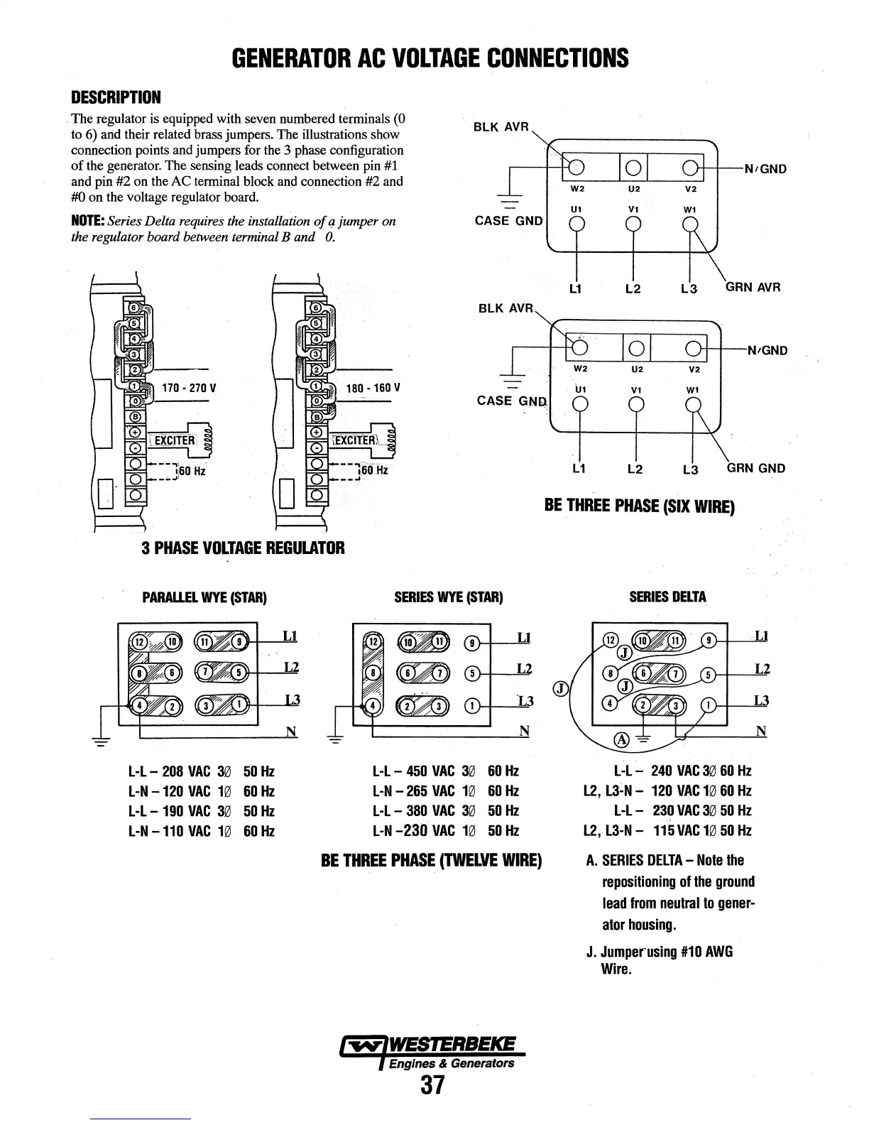
DESCRIPTION
.
The
regulator is equipped with seven numbered terminals (0
to 6) and their related brass jumpers. The illustrations show
connection points and jumpers for the 3 phase configuration
of
the generator. The sensing leads connect between pin #1
and pin
#2 on the
AC
terminal block and connection #2 and
#0
on
the voltage regulator board.
NOTE:
Series Delta requires the installation
of
q jumper on
the regulator board between terminal B and
0.
170
•
270V
180
·160V
BLK
AVR
CASE GND
Ut
Vt
L1
L2
L3
GRN
AVR
Vt
CASE
GN~
3
PHASE
VOLTAGE
REGULATOR
PARALLR
WYE
(STAR)
L-L-
208
VAC
30
50
Hz
L-N
-120
VAC
10
60
Hz
L·L-
190
VAC
30
50
Hz
L-N
-110
VAC
10
60
Hz
SERIES
WYE
(STAR)
L-L
-
450
VAC
30
60
Hz
L-N
-
265
VAC
10
60
Hz
L-L-
380
VAC
30
50
Hz
L-N
-2:30
VAC
10
50
Hz
BE
THREE
PHASE
(TWELVE
WIRE)
1-.v-IWESTERBEKE
l Engines & Generators
37
L1
L2
L3
GRN
GND
BE
THREE
PHASE
(SIX
WIRE)
SERIES
DELTA
L·L-
240
VAC
3060Hz
L2,
L3~N
-
120
VAC
10
60
Hz
L·L-
230
VAC
3050Hz
l2, L3-N-
115
VAC
1050Hz
A.
SERIES
DELTA-
Note
the
repositioning
of
the
ground
lead
from
neutral
to
gener-
ator
housing.
J.
Jumperusing
#10
AWG
Wire.