DC
ELECTRICAL
SYSTEM/ALTERNATOR
DESCRIPTION
The
charging system consists
of
an alternator with a voltage
regulator, an engine
DC
wiring harness, a mounted
DC
cir-
cuit breaker, and a battery with connecting cables. Because
of
the use
of
integrated circuits (IC's) the electronic voltage
regulator is very compact and is mounted internally
or
on the
back
of
the alternator.
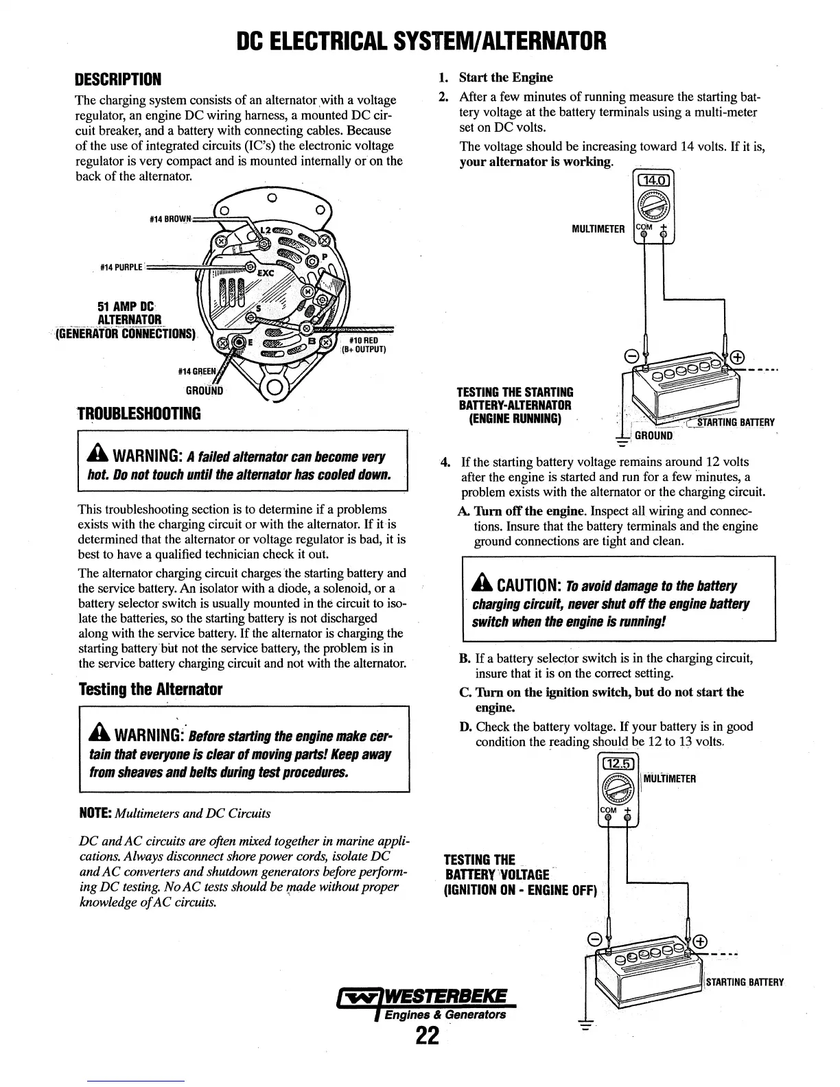
51
AMP
DC
ALTERNATOR
(GENERA'rblfCONNE-CTIONS).
TROUBLESHOOTING
A
WARNING:
A
failed
alternator
can
become
very
hot.
Do
not
touch
until
the
alternator
has
cooled
down.
This troubleshooting section is to determine
if
a problems
exists with the charging circuit or with the alternator.
If
it is
determined that the alternator or voltage regulator is bad, it is
best to have a qualified technician check it out.
The
alternator charging circuit charges the starting battery and
the service battery.
An
isolator with a diode, a solenoid, or a
battery selector switch is usually mounted in the circuit to iso-
late the batteries, so the starting battery is not discharged
along with the service battery.
If
the alternator is charging the
starting battery but not the service battery, the problem is in
the service battery charging circuit and not with the alternator.
Testing
the
Alternator
A
WARNING:·
Before
starting
the
engine
make
cer·
tain
that
everyone
is
clear
of
moving
parts!
Keep
away
from
sheaves
and
belts
during
test
procedures.
NOTE:
Multimeters and
DC
Circuits
DC
andAC
circuits are often mixed together in marine appli-
cations. Always disconnect shore power cords, isolate
DC
and A C converters and shutdown generators before perform-
ing
DC
testing.
NoAC
tests should
be
r,nade
without proper
knowledge
of
AC
circuits. .
1.
Start the Engine
2. After a few minutes
of
running measure the starting bat-
tery voltage at the battery terminals using a multi-meter
set on
DC
volts.
The voltage should
be
increasing toward
14
volts.
If
it is,
your alternator
is
working.
(14.0)
0
MULTIMETER
COM
+
TESTING
THE
STARTING
BATTERY-ALTERNATOR
(ENGINE
RUNNING)
4.
If
the starting battery voltage remains around 12 volts
after the engine is started and run for a few minutes, a
problem exists with the alternator or the charging circuit.
A.
Thm
off the engine. Inspect all wiring and connec-
tions. Insure that the battery terminals and the engine
ground connections are tight and clean.
A
CAUTION:
To
avoid
damage
to
the
battery
·
charging
circuit,
never
shut
off
the
engine
battery
switch
when
the
engine
is
running!
B.
If
a battery selector switch is in the charging circuit,
insure that it is on the correct setting.
C.
Thm
on the ignition switch, but do not start the
engine.
D. Check the battery voltage.
If
your battery is in good
condition the reading should
be
12 to 13 volts.
(12.5)
0 I
MULTIMETER
COM
+
TESTING
THE
BATTERY
·,VOLTAGE
-
(IGNITION
ON
•
ENGINE
OFF)
.
Engines & Generators
22