FRONT
CASE
I
COUNTERBALANCE
SHAFT
AND
OIL
PUMP
INSTALLATION
Counterbalance
Rear
Bearing
1. Install the special tool guide pins (bearing Installer) in the
tapered hole
of
the cylinder block as shown .
. \
t)r---,
(
OIL
HOLE
~
~
J
0..
r
\
'-
"::J
~\
BEARING
2. Mate the ratchet ball
of
the bearing in the oil hole
of
the
rear bearing and install the bearing in the bearing
installer.
3. Apply clean engine oil to the outer circumference
of
the
bearing and the bearing hole in the cylinder block.
4.
GUIDE
PIN
-
__
.v
\
Counterbalance
Front
Bearing
1. Apply engine oil to the bearing outer circumference and
the bearing hole in the cylinder block.
2. Press-in the front bearing using the installer tool.
FRONT
BEARING
INSTALLATION
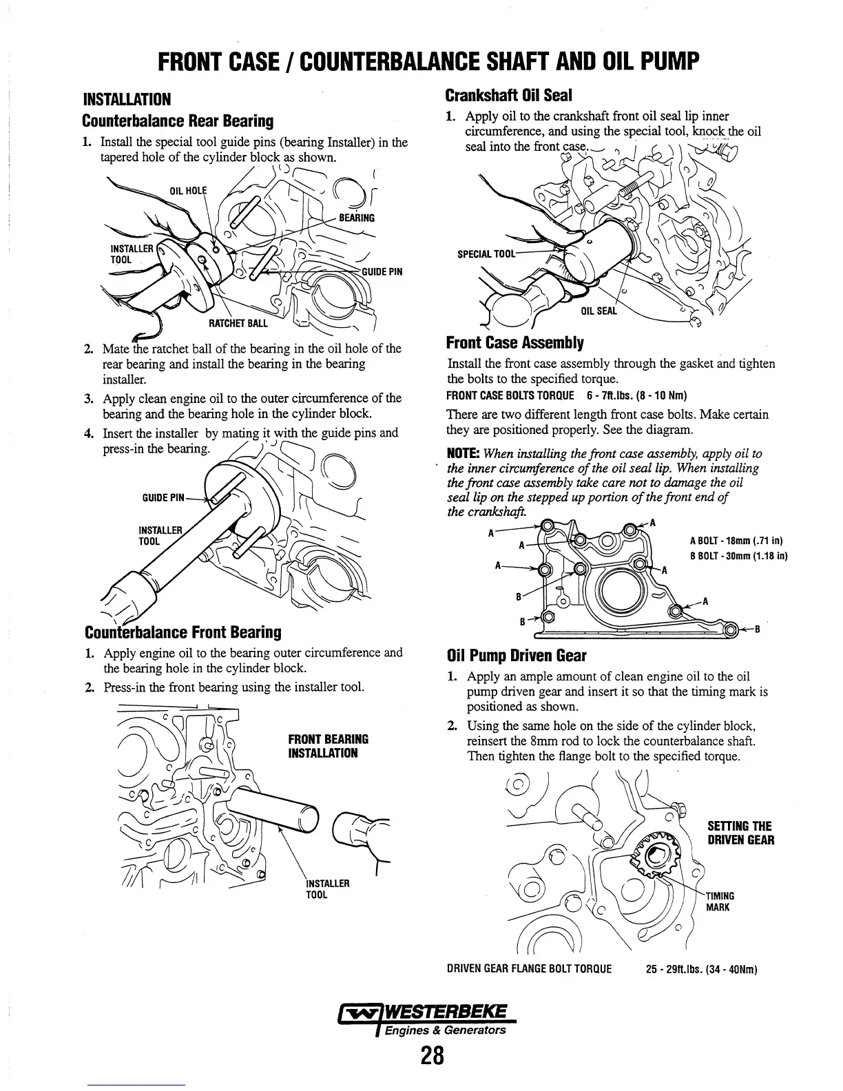
Crankshaft
Oil
Seal
1.
Front
Case
Assembly
Install the front case assembly through the gasket and tighten
the bolts to the specified torque.
FRONT
CASE
BOLTS
TORQUE
6 -
7ft.Jbs.
(8
-10
Nm)
There are two different length front case bolts. Make certain
they are positioned properly. See the diagram.
NOTE:
When
installing
the
front case
assembly,
apply
oil
to
the inner circumference
of
the
oil seal
lip.
When
installing
the front
case
assembly take
care
not
to
damage
the
oil
seal
lip
on
the stepped
up
portion
of
the front end
of
the crankshaft.
A
A_-.r.-
B
B
Oil
Pump
Driven
Gear
A
BOLT
•
18mm
(.71
in)
B
BOLT·
30mm
(1.18
in)
B
1.
Apply an ample amount
of
clean engine oil to the oil
pump driven gear and insert it so that the timing mark is
positioned as shown.
2.
Using the same hole on the side
of
the cylinder block,
reinsert the 8mm rod to lock the counterbalance shaft.
Then tighten the flange bolt to the specified torque.
DRIVEN
GEAR
FLANGE
BOLT
TORQUE
SETTING
THE
DRIVEN
GEAR
TIMING
MARK
25
-
29ft.lbs.
(34·
40Nm)
Engines & Generators
28