PISTONS
AND
CONNECTING
RODS
ARROW
FRONT
MARK
II
NUMBERS
INDICATE
THE
SUGGESTED
ORDER
OF
DISASSEMBLY
gOILRING
6
BEARING
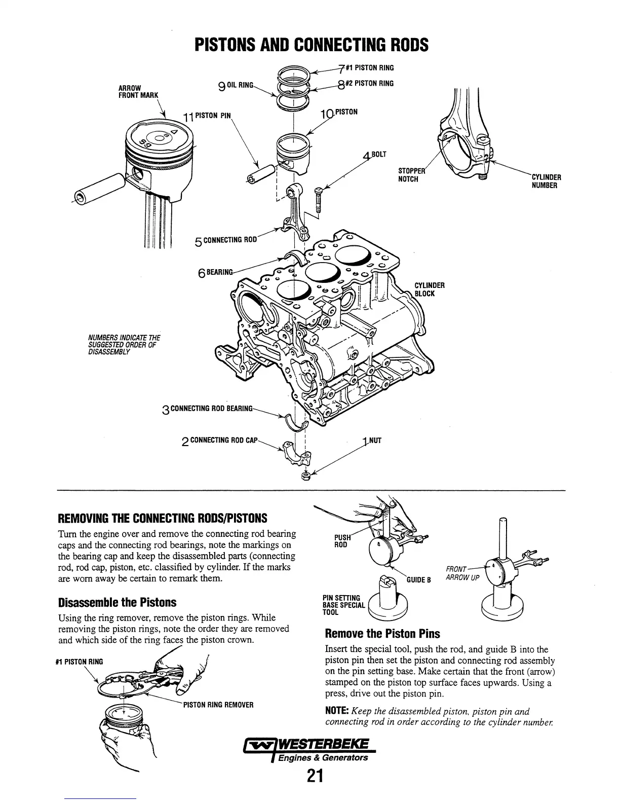
REMOVING
THE
CONNECTING
RODS/PISTONS
Turn
the
engine over and remove the connecting rod bearing
caps and
the
connecting rod bearings, note the markings
on
the bearing cap
and
keep the disassembled parts (connecting
rod, rod
cap,
piston, etc. classified
by
cylinder.
If
the marks
are
worn
away
be
certain to remark them.
Disassemble
the
Pistons
Using the
ring
remover, remove the piston rings. While
removing
the
piston rings, note the order they are removed
and which side of
the
ring faces the piston crown.
#1
PISTON
RING
#2
PISTON
RING
STOPPER
NOTCH
~
GUIDEB
PINSmlNG
BASE
SPECIAL
---'.
TOOL
Remove
the
Piston
Pins
CYUNDER
NUMBER
Insert the special tool, push the rod, and guide B
into
the
piston pin then set
the
piston and connecting rod assembly
on the pin setting base. Make certain that the front
(arrow)
stamped on the piston
top
surface faces upwards.
Using
a
press, drive out the piston pin.
NOTE:
Keep
the
disassembled piston, piston pin and
connecting
rod
in
order according
to
the
cylinder
number.
Engines & Generators
21