PISTONS
AND
CONNECTING
RODS
PISTON
PIN
INSPECTION
Reinsert the piston pin into the piston hole with your thumb.
You
should feel a slight resistance,
if
the bore is misaligned
the pin will click or bind as it enters.
Try the pin from both
sides. Replace the piston
if
the pin can be too easily inserted
or if there
is
excessive play.
NOTE:
The
piston
pin and piston
are
replaced
as
an
assembly.
Measure the outside diameter
of
the piston pin.
PISTON
PIN
0.0.0.6300
-
0.6302io
(16.001
-16.007mm)
Pistons
Check the piston surfaces for wear, seizure, cracks and
streaking.
If
any damage is evident, replace the piston.
Inspect the oil return hole in the oil ring groove and the oil
hole in the piston boss. Clean the piston
if
these are clogged.
Check the piston pin hole for signs
of
seizure or damage.
Replace the piston
if
damage is
evident
Measure the piston
diameter at
90° (perpendicular) to the pin bore axis.
PISTON
0.0.2.5579
-
2.5591io
(64.97
-
65.00mm)
If
the piston diameter is less then the standard replace
the piston.
NOTE:
The
piston and piston pin
are
replaced
as
an
assembly.
Piston
Rings
Insert the piston ring into the cylinder bore placing it against
the top
of
the piston head and pressing it in. When it marks a
right angle, measure the piston ring gap with a feeler gauge.
When the gap is too large, replace the piston ring.
PISTON
RING
GROOVE
staodard
No.1
0.0480
-
0.048810
(1.22
-
1.24mm)
No
2
0.0476
-
O.0484io
(1.21
-1.23mm)
Oil
0.1108
-
0.1116io
(2.815
-
2.835mm)
PISTON
RING
END
GAP
No.1
No.2
Oil
PISTON
staodard
0.0059
-
0.0118io
(0.15
-
0.30mm)
0.0138
-
0.0197io
(0.35
-
0.50mm)
0.008
-
0.028io
(0.2
-
0.7mm)
Limit
0.810
(0.0315mm)
0.8io
(0.0315mm)
1.0io
(0.0394mm)
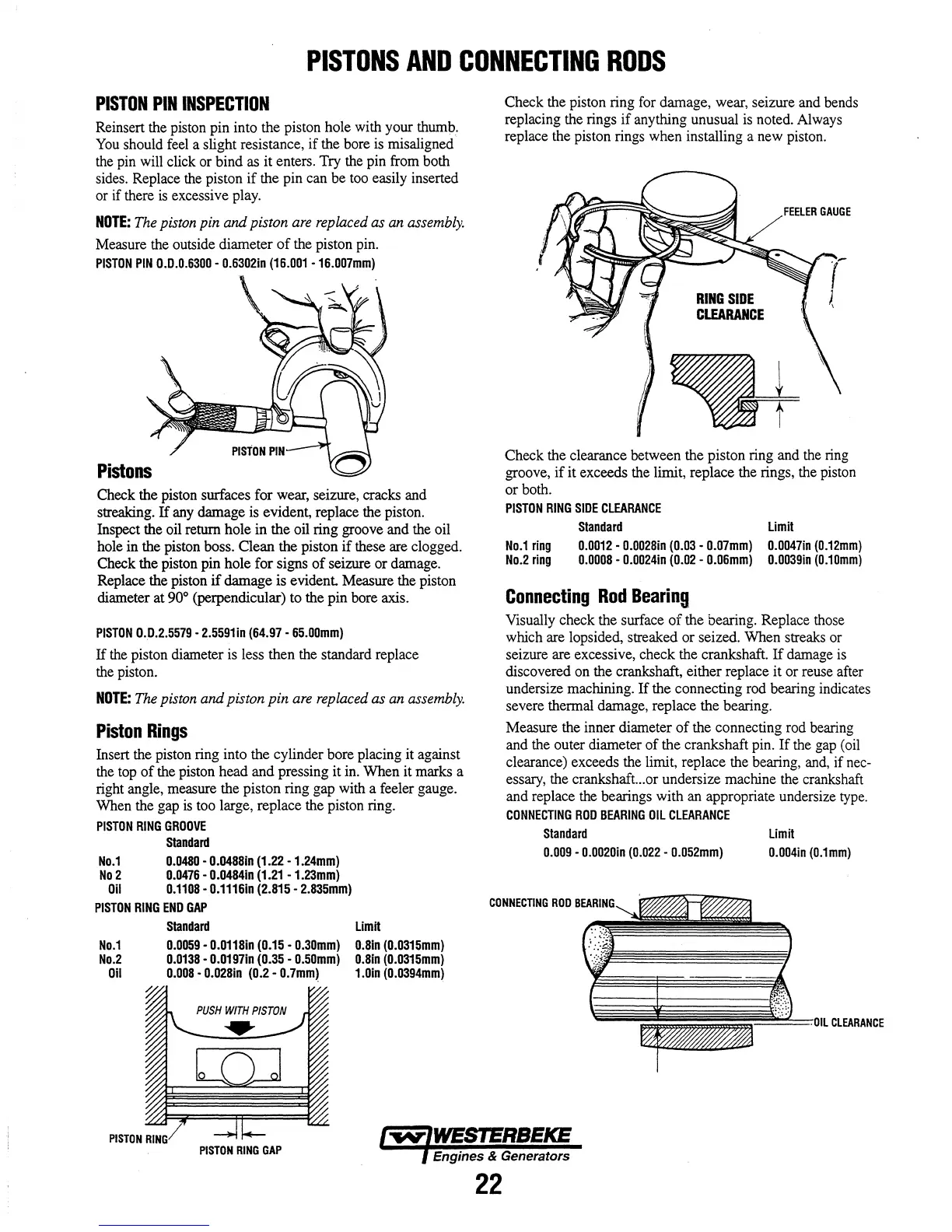
Check the piston ring for damage, wear, seizure and bends
replacing the rings
if
anything unusual is noted. Always
replace the piston rings when installing a new piston.
RING
SIDE
ClEARANCE
FEELER
GAUG
E
Check the clearance between the piston ring and the ring
groove,
if
it exceeds the limit, replace the rings, the piston
or
both.
PISTON
RING
SIDE
CLEARANCE
Staodard
Limit
No.1
riog
No.2
riog
0.0012
-
0.0028io
(0.03
-
0.07mm)
0.0047io
(0.12mm)
0.0008
-
0.0024io
(0.02
-
0.06mm)
0.0039io
(0.10mm)
Connecting
Rod
Bearing
Visually check the surface
of
the bearing. Replace those
which are lopsided, streaked
or
seized. When streaks or
seizure are excessive, check the crankshaft.
If
damage is
discovered on the crankshaft, either replace
it
or reuse after
undersize machining.
If
the connecting rod bearing indicates
severe thermal damage, replace the bearing.
Measure the inner diameter
of
the connecting rod bearing
and the outer diameter
of
the crankshaft pin.
If
the gap (oil
clearance) exceeds the limit, replace the bearing, and,
if
nec-
essary, the crankshaft...or undersize machine the crankshaft
and replace the bearings with an appropriate undersize type.
CONNECTING
ROD
BEARING
OIL
CLEARANCE
Staodard
Limit
0.009
-
0.0020io
(0.022
-
0.052mm)
0.004io
(0.1mm)
CONNECTING
ROD
Y~'''''''''
.....
PISTON
RING
GAP
Engines & Generators
22