ENGINE
ADJUSTMENTS
NOTE:
WESTERBEKE recommends that the following
engine adjustments be performed by a competent engine
,mechanic. The information below is provided to assist the
mechanic.
ENGINE
SPEED
(HERTZ)
ADJUSTMENT
Governor
The belt-driven, mechanically operated governor maintains
the engine's rpm under various load conditions. Engine speed
determines the hertz and voltage output of the generator.
Governor
Adiusbnents
Operate the generator to bring the unit
up
to operating tem-
perature before adjusting the governor.
NOTE:
If
the
governor is severely out
of
adjustment, manually
adjust the linkage at no-load
to
obtain a safe output voltage
before proceeding with the adjustment.
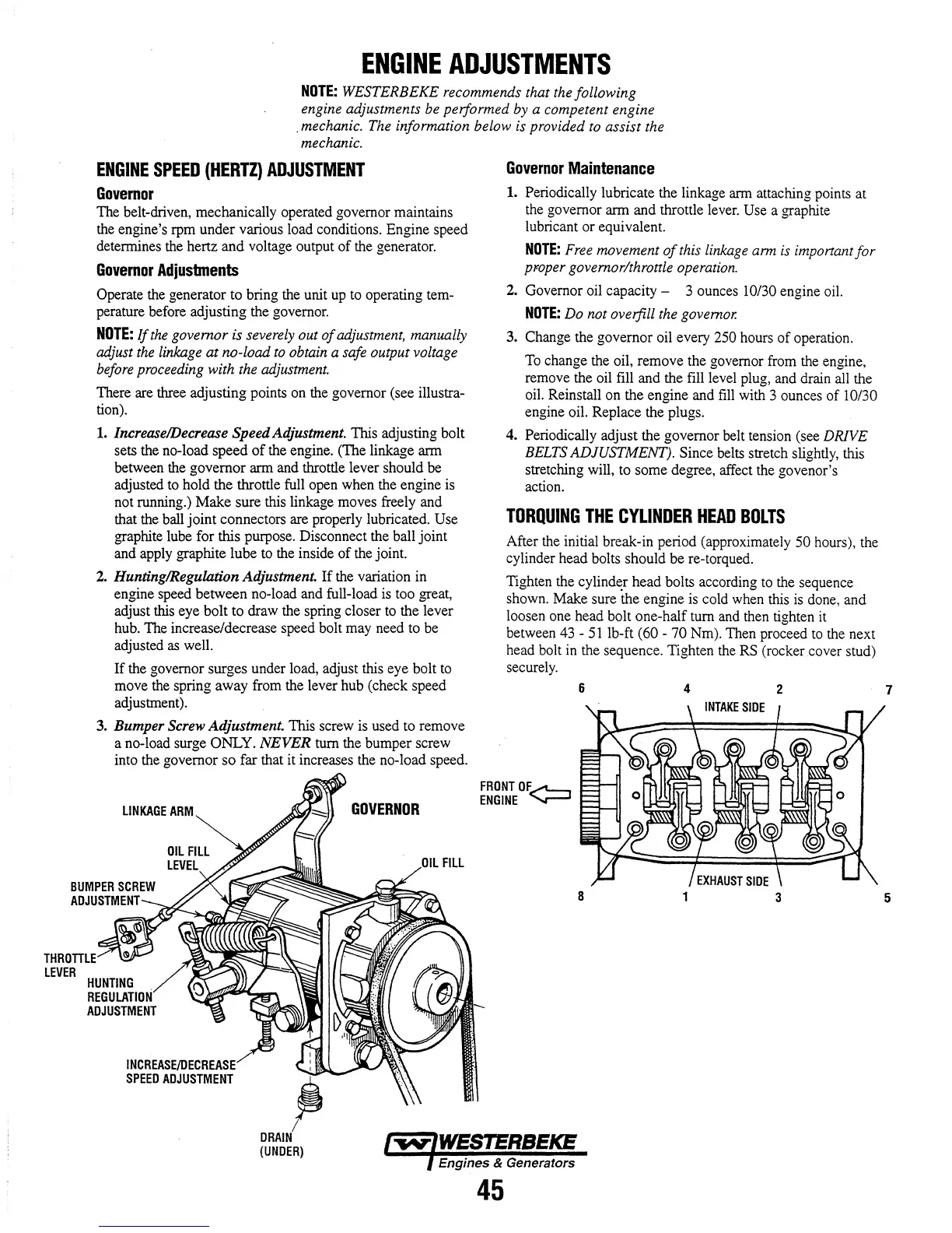
There are three adjusting points on the governor (see illustra-
tion).
1.
Increase/Decrease Speed Adjustment. This adjusting bolt
sets the no-load speed
of
the engine. (The linkage arm
between the governor arm and throttle lever should be
adjusted to hold the throttle full open when the engine
is
not running.) Make sure this linkage moves freely and
that the ball joint connectors are properly lubricated. Use
graphite lube for this purpose. Disconnect the ball joint
and apply graphite lube to the inside
of
the joint.
2.
Hunting/Regulation Adjustment.
If
the variation in
engine speed between no-load and full-load
is
too great,
adjust this eye bolt to draw the spring closer
to
the lever
hub. The increase/decrease speed bolt may need to be
adjusted
as
well.
If the governor surges under load, adjust this eye bolt
to
move the spring away from the lever hub (check speed
adjustment).
3.
Bumper Screw Adjustment. This screw
is
used to remove
a no-load surge
ONLY.
NEVER
turn the bumper screw
into the governor so far that it increases the no-load speed.
LINKAGE
ARM
INCREASEf[IECFIEA~;E
SPEED
ADJUSTMENT
GOVERNOR
L
FILL
Governor
Maintenance
1.
Periodically lubricate the linkage arm attaching points at
the governor arm and throttle lever.
Use a graphite
lubricant or equivalent.
NOTE:
Free movement
of
this linkage arm
is
important
for
proper governor/throttle operation.
2. Governor oil capacity - 3 ounces 10/30 engine oil.
NOTE:
Do not overfill the governor.
3. Change the governor oil every 250 hours
of
operation.
To
change the oil, remove the governor from the engine,
remove the oil fill and the fill level plug, and drain all the
oil. Reinstall on the engine and
fill
with 3 ounces
of
I 0/30
engine oil. Replace the plugs.
4. Periodically adjust the governor belt tension (see
DRIVE
BELTS ADJUSTMENT). Since belts stretch slightly, this
stretching will, to some degree, affect the govenor's
action.
TORQUING
THE
CYLINDER
HEAD
BOLTS
After the initial break-in period (approximately 50 hours), the
cylinder head bolts should be re-torqued.
Tighten the cylinder head bolts according to the sequence
shown. Make sure
the engine
is
cold when this
is
done, and
loosen one head bolt one-half turn and then tighten it
between
43
-
51
lb-ft (60 - 70 Nm). Then proceed
to
the next
head bolt
in
the sequence. Tighten the
RS
(rocker cover stud)
securely.
FRONTOF~
ENGINE
'-r-'
6
4
2
(UNDER)
Engines & Generators
45
7