ENGINE
ADJUSTMENTS
NOTE:
WESTERBEKE
recommends
that
the
following
engine
adjustments
be
performed
by
a competent
engine
mechanic.
The
information below
is
provided
to
assist
the
mechanic.
VALVE
CLEARANCE
ADJUSTMENT
NOTE:
Retorque
the
cylinder head bolts before adjusting
the
engine's
valves
(see
TORQUING
THE CYUNDER
HEAD
BOLTS).
1.
Remove the rocker cover and gasket.
2. Rotate the crankshaft in the normal direction
of
rotation,
placing the No. 1 piston at the top
of
its compression
stroke with the exhaust and intake valves completely
closed. Adjust the intake and exhaust valves for No. 1
cylinder, the exhaust valve for
No.2
cylinder, and the
intake valve for
No.3
cylinder (see chart).
3. Rotate the crankshaft
180° in its normal direction
of
rotation. Locate the piston in No. 1 cylinder at the top
of
its exhaust stroke. Adjust the intake valve for
No.2
cylinder and the exhaust valve for
No.3
cylinder (see
chart).
CYLINDER
#
CRANK
ANGLE
1 2 3
When
No.
1
piston
is
set
at
top
of
IN
•
•
compression
stroke
•
•
EX
When
No.
1
piston
is
positioned
IN
•
at
top
of
exhaust
stroke
EX
•
4
••
Replace the rocker cover along with a new rocker cover
gasket..
Rocker
cover
torque:
2.9-5.1
Ib-n
(4
- 7
Nm)
VALVE
CLEARANCE
Valve
Clearance:
Intake
0.20mm
(.008
inches)
Exhaust
0.30mm
(.0012
inches)
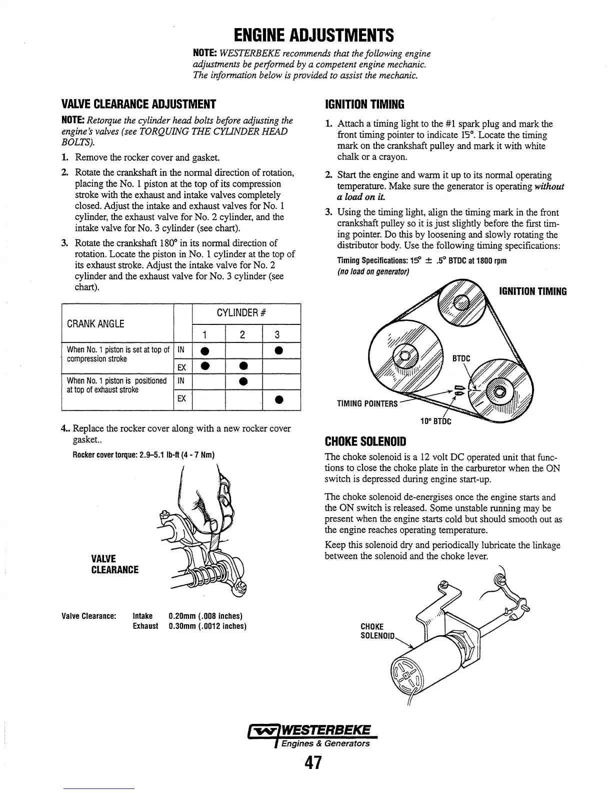
IGNITION
TIMING
1.
Attach a timing light to the #1 spark plug and mark the
front timing pointer to indicate
1'5°.
Locate the timing
mark on the crankshaft pulley and mark it with white
chalk or a crayon.
2.
Start
the engine and warm it up to its normal operating
temperature. Make sure the generator is operating without
a load
on
it.
3. Using the timing light, align the timing mark in the front
crankshaft pulley so it is
just
slightly before the
fITSt
tim-
ing pointer. Do this by loosening and slowly rotating the
distributor body.
Use the following timing specifications:
Timing
Specifications:
15' ±
.5°
BTDC
at
1800
rpm
(no
load
on
generator)
IGNITION
TIMING
CHOKE
SOLENOID
The choke solenoid is a
12
volt
DC
9perated unit that func-
tions to close the choke plate in the carburetor when the
ON
switch is depressed during engine start-up.
The choke solenoid de-energises once the engine starts and
the
ON
switch
is
released. Some unstable running may be
present when the engine starts cold but should smooth out
as
the engine reaches operating temperature.
Keep this solenoid
dry and periodically lubricate the linkage
between the solenoid and the choke lever.
CHOKE
SOLENOID
Engines & Generators
47