PISTONS
AND
CONNECTING
RODS
NOTE:
See
Crankshaft/Bearing section for measuring
the
oil
clearance
with
a Plastigauge.
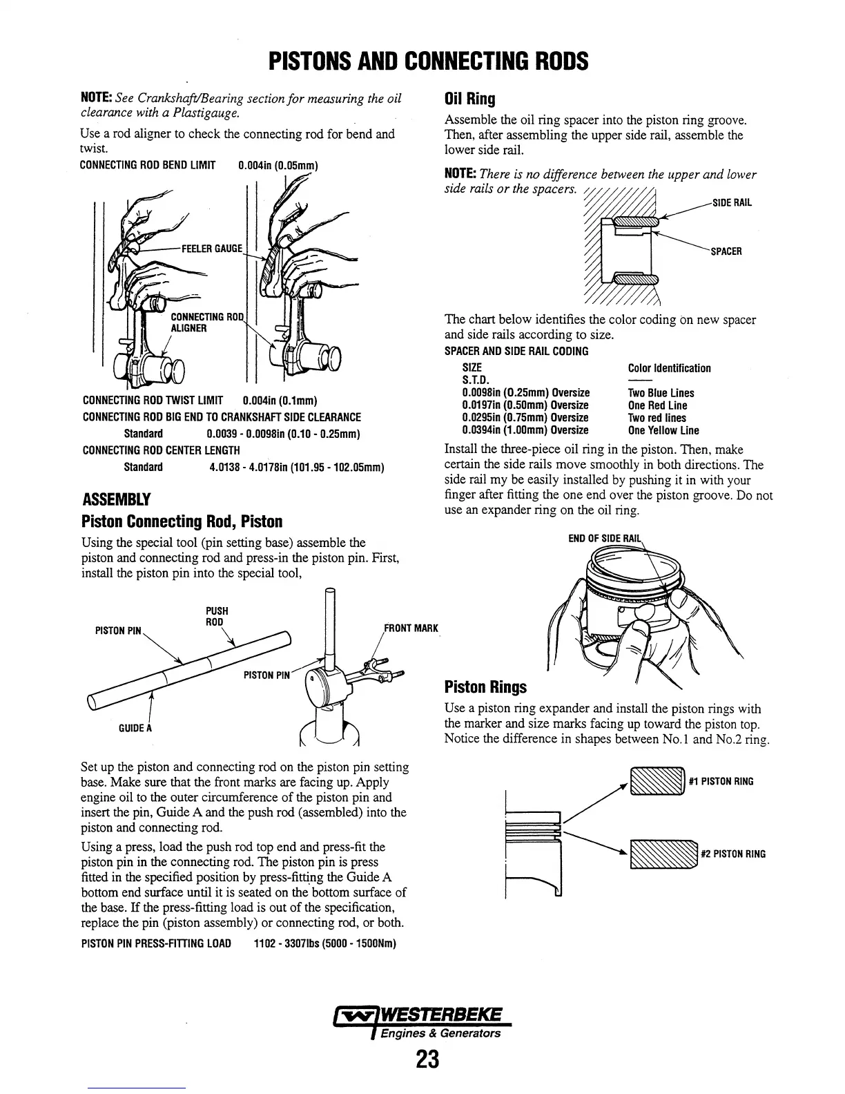
Use a rod aligner to check the connecting
rod
for bend and
twist.
CONNECTING
ROD
BEND
LIMIT
0.004in
(O.OSmm)
CONNECTING
ROD
TWIST
LIMIT
0.004in
(0.1mm)
CONNECTING
ROD
BIG
END
TO
CRANKSHAFT
SIDE
CLEARANCE
Standard
0.0039
-
0.0098in
(0.10
-
0.2Smm)
CONNECTING
ROD
CENTER
LENGTH
Standard
4.0138
-
4.0178in
(101.9S
-102.0Smm)
ASSEMBLY
Piston
Connecting
Rod,
Piston
Using the special tool (pin setting base) assemble the
piston and connecting
rod
and press-in the piston pin. First,
install the piston pin into the special tool,
GUIDE
A
PUSH
ROD
FRONT
MARK
Set up the piston
and
connecting rod on the piston pin setting
base. Make sure that the front marks are facing up. Apply
engine oil to the outer circumference
of
the piston pin and
insert the pin, Guide A and the push rod (assembled) into the
piston and connecting rod.
Using a press, load the push rod top
end
and press-fit the
piston pin in the connecting rod. The piston pin is press
fitted in the specified position
by
press-fini:ng the Guide A
bottom end surface until it is seated on the bottom surface
of
the base.
If
the press-fitting load is out
of
the specification,
replace the pin (piston assembly)
or
connecting rod, or both.
PISTON
PIN
PRESS-FITTING
LOAD
1102
-
33071bs
(SOOO
-1S00Nm)
Oil
Ring
Assemble the oil ring spacer into the piston ring groove.
Then, after assembling the upper side rail, assemble the
lower side rail.
NOTE:
There
is
no
difference between
the
upper and
lower
side
rails
or
the
spacers.
W~-j/
//,
m
SIDE
RAIL
~~,......-
'-----~
SPACER
The chart below identifies the color coding on new spacer
and side rails according to size.
SPACER
AND
SIDE
RAIL
CODING
SIZE
Color
Identification
S.T.D.
0.0098in
(O.2Smm)
Oversize
Two
Blue
Lines
0.0197in
(O.SOmm)
Oversize
One
Red
Line
0.029Sin
(0.7Smm)
Oversize
Two
red
lines
0.D394in
(1.00mm)
Oversize
One
Yellow
Line
Install the three-piece oil ring in the piston. Then, make
certain the side rails
move
smoothly in both directions. The
side rail
my
be easily installed by pushing it in with your
finger after fitting the one
end
over the piston groove. Do not
use an expander ring on the oil ring.
END
OF
SIDE
RAIL
Piston
Rings
Use a piston ring expander and install the piston rings with
the marker and size marks facing up toward the piston top.
Notice the difference in shapes between No.1 and No.2 ring.
1--
__
.,/-"
PlSTDO
ROG
~~#2PISTONRING
Engines & Generators
23