Installation en
Installation and operating instructions Wilo-Control EC-L 71
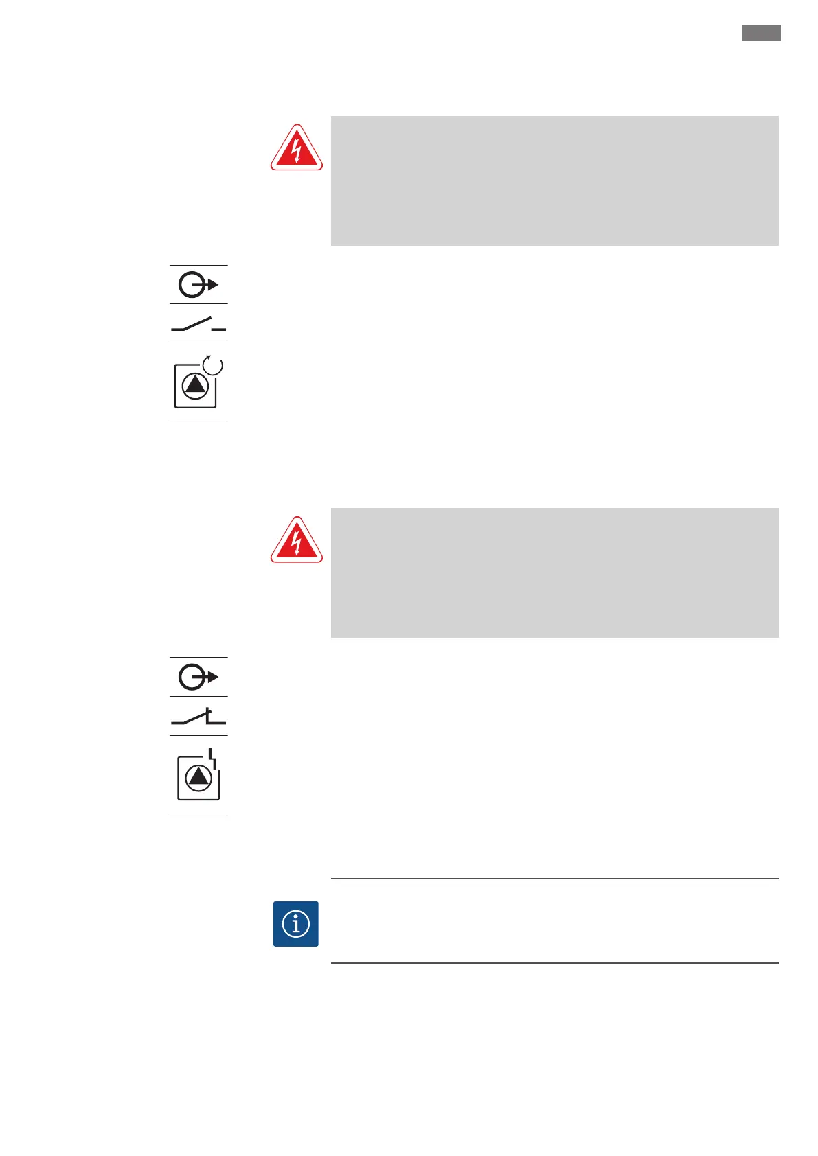
6.5.14 Individual run signal (EBM) con-
nection
DANGER
Risk of fatal injury due to an external electrical current source!
The power supply comes from an external source. This voltage is also present at the
terminals when the main switch is switched off! There is a risk of fatal injury! The
power supply must be disconnected from its source before commencing any work!
Electrical work must be carried out by a qualified electrician in accordance with the
locally applicable regulations.
Fig.21: Overview of connection symbol
A run signal is output for each pump (EBM) via a separate output:
▪Contact: potential-free NO contact
▪Switching capacity: 250V, 1A
Insert the connection cable laid by the customer through the threaded cable connec-
tions and secure. Connect the wires to the terminal strip according to the connection
diagram. For details on the terminal number, see the overview of connections in the
cover. The “x” in the symbol states the respective pump:
▪1=pump 1
▪2=pump 2
▪3=pump 3
6.5.15 Individual fault signal (ESM) con-
nection
DANGER
Risk of fatal injury due to an external electrical current source!
The power supply comes from an external source. This voltage is also present at the
terminals when the main switch is switched off! There is a risk of fatal injury! The
power supply must be disconnected from its source before commencing any work!
Electrical work must be carried out by a qualified electrician in accordance with the
locally applicable regulations.
Fig.22: Overview of connection symbol
A fault message is output for each pump (ESM) via a separate output:
▪Contact: potential-free NC contact
▪Switching capacity: 250V, 1A
Insert the connection cable laid by the customer through the threaded cable connec-
tions and secure. Connect the wires to the terminal strip according to the connection
diagram. For details on the terminal number, see the overview of connections in the
cover. The “x” in the symbol states the respective pump:
▪1=pump 1
▪2=pump 2
▪3=pump 3
6.5.16 Connecting an external alarm sig-
nal
NOTICE
Do not apply external voltage!
An external voltage which is applied destroys the component.