Commissioning en
Installation and operating instructions Wilo-Control EC-L 79
▶ The switchgear is ready for operation, start the initial configuration or automatic
mode.
Display with level sensor or dynamic pressure bell
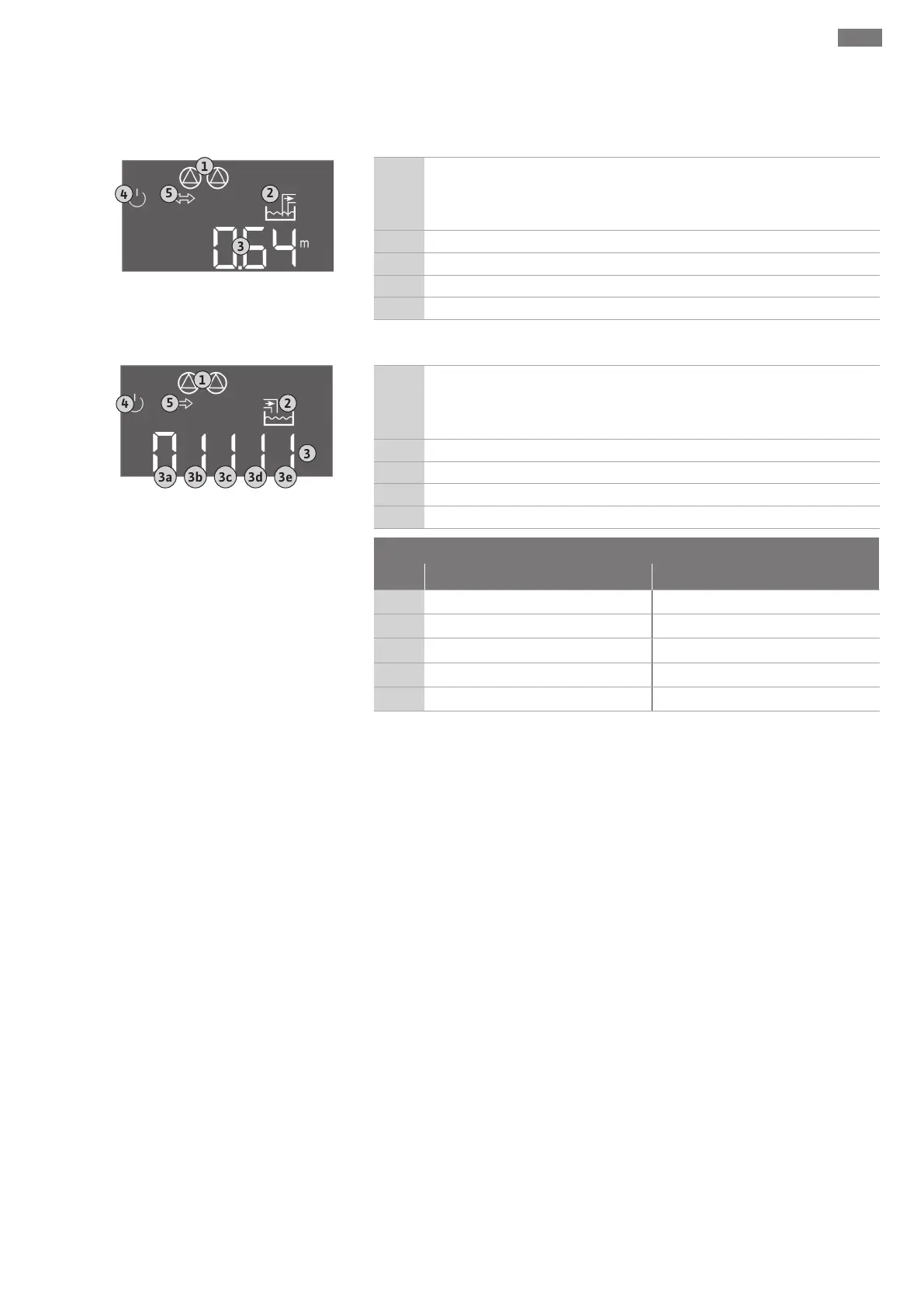
Fig.29: Start screen: Level sensor/dynamic
pressure bell
1
Current pump status:
– Number of registered pumps
– Pumps activated/deactivated
– Pumps On/Off
2 Set operating mode (e.g. drain)
3 Current water level in m
4 Standby: Switchgear is ready for operation.
5 Field bus active
Display with float switch
Fig.30: Start screen: Float switch
1
Current pump status:
– Number of registered pumps
– Pumps activated/deactivated
– Pumps On/Off
2 Set operating mode (e.g. fill)
3 Switching state of the float switch
4 Standby: Switchgear is ready for operation.
5 Field bus active
Switching state of the float switch depending on the operating mode
No. drain fill
3a
High water level High water level
3b
Pump 2 On Pump 1 and 2 Off
3c
Pump 1 On Pump 1 On
3d
Pump 1 and 2 Off Pump 2 On
3e
Dry-running level Min. level (low water)
8.5 Start initial configuration
Observe the following points during the configuration:
▪If there is no input or operation for 6minutes:
– The display illumination is switched off.
– The display shows the main screen again.
– Parameter input is locked.
▪Some settings can only be changed when all pumps are off.
▪The display illumination switches off automatically if not operated for one minute.
▪The menu adapts automatically, based on the settings. Example: Menu 1.12 is only vis-
ible if the level sensor has been activated.
▪The menu structure applies to all EC switchgears (e.g. EC-Lift, EC-Fire). This may lead
to gaps in the menu structure.
As standard, the values are only displayed. To change values, the parameters in menu
7.01 must be enabled: