en Commissioning
80 WILO SE 2018-12
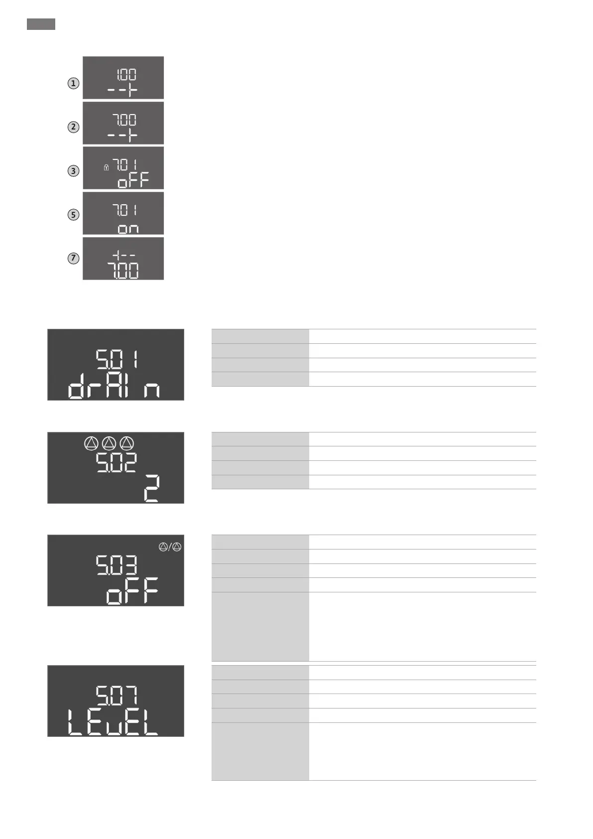
Fig.31: Parameter input enabled
1. Press the operating button for 3s.
⇒ Menu item 1.00 appears
2. Turn the operating button until menu 7 appears.
3. Press the operating button.
⇒ Menu 7.01 appears.
4. Press the operating button.
5. Change value to “on”: Turn the operating button.
6. Save value: Press the operating button.
⇒ The menu is enabled and can be changed.
7. Turn the operating button until the end of menu 7 appears.
8. Press the operating button.
⇒ Back to the main menu level.
▶ Start initial configuration:
– Menu 5: Basic settings
– Menu1: Switch-on/off values
– Menu2: Field bus connection (if applicable)
- Menu 3: Enable pumps
Menu 5: Basic settings
Fig.32: Menu 5.01
Menu no. 5.01
Description Operating mode
Value range fill (fill), drain (drain)
Factory setting drain
Fig.33: Menu 5.02
Menu no. 5.02
Description Number of connected pumps
Value range 1 … 3
Factory setting 2
Fig.34: Menu 5.03
Menu no. 5.03
Description Standby pump
Value range on, off
Factory setting off
Explanation
One pump can be used as the standby pump. This pump is
not activated in normal operation. The standby pump is
only activated in the event of pump failure due to a fault.
The standby pump is subject to standstill monitoring. The
standby pump is therefore activated during pump cycling
and pump kick.
Fig.35: Menu 5.07
Menu no. 5.07
Description Signal transmitter for level measurement
Value range Float, Level, Bell, Opt01
Factory setting Level
Explanation
Definition of the signal transmitters for level measurement:
- Float = float switch
- Level = level sensor
- Bell = dynamic pressure bell
- Opt01 = NW16 level monitor