Appendix en
Installation and operating instructions Wilo-Control EC-L 99
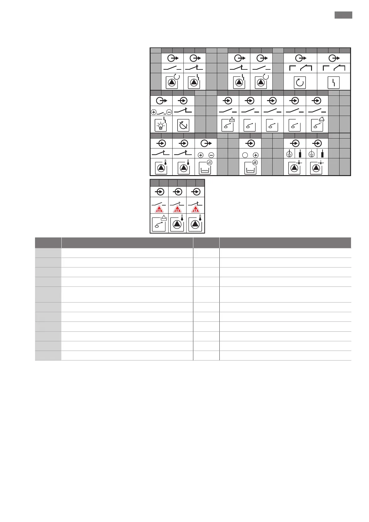
Wiring diagram EC-L1... and EC-L2...
1 2 3 4 5 6 7 8 9 10 11 12 13 14 15 16 17 18
19 20 21 22 23 24 25 26 27 28 29 30 31 32 33 34 35 36
37 38 39 40 41 42 43 44 45 46 47 48 49 50 51 52 53 54
1
off
4-20 mA
In
!
1 1
1 2
1
+
2
2
on
2
on
1
2 2
0-10 V
24 V
55 56 57 58 59 60
1 2
!
Terminal Function Terminal Function
2/3
Output: Individual run signal pump 1 31/32 Input: “Pump 2 on” float switch
4/5
Output: Individual fault signal pump 1 33/34 Input: “High water” float switch
8/9
Output: Individual fault signal pump 2 37/38 Input: Thermal winding monitor pump 1
10/11
Output: Individual run signal pump 2 39/40 Input: Thermal winding monitor pump 2
13/14/15
Output: Collective run signal 41/42 Output: Analogue output for displaying the actual level
value
16/17/18
Output: Collective fault signal 45/46 Input: Level sensor 4–20 mA
19/20
Output: Power output 49/50 Input: Leakage detection pump 1
21/22
Input: Extern OFF 51/52 Input: Leakage detection pump 2
25/26
Input: “Dry-running protection” float switch 55/56 Input: “Dry-running protection” float switch (ex-mode)
27/28
Input: “All pumps off” float switch 57/58 Input: Thermal winding monitor pump 1 (ex-mode)
29/30
Input: “Pump 1 on” float switch 59/60 Input: Thermal winding monitor pump 2 (ex-mode)