Do you have a question about the Woodward DTSC-200A and is the answer not in the manual?
Read manual, follow safety instructions, prevent injury/damage.
Unauthorized modifications cause injury, damage, and void warranty.
Precautions for handling electronic controls to prevent damage.
Check website for latest revision of this publication.
Explanation of WARNING, CAUTION, and NOTE symbols and their meanings.
List of related Woodward manuals for DTSC-200A.
Specifies the intended operational uses for the DTSC-200A unit.
Manual covers all options; ignore features not present on your unit.
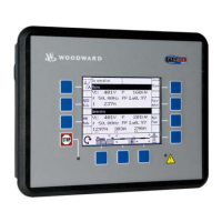
Explanation of the DTSC-200A front panel components and LC display.
Description of the status indicated by each LED on the front panel.
Details on remaining LEDs and operation of BYPASS/SETTINGS buttons.
How to initiate and confirm a LOAD TEST sequence.
How to initiate and confirm an ENGINE TEST sequence.
Functionality of acknowledge button and navigating alarm lists.
Detailed explanation of icons used for navigation functions.
Explanation of the Home Page layout and its display fields.
Display of voltage, current, power, phase rotation for Sources 1 and 2.
Shows phase currents for Source 1 and Source 2 with slave pointer.
Details on battery voltage, discrete I/O status, and time/date displays.
Overview of LogicsManager groups and system counter displays.
Displays unacknowledged alarms with text, date, and time stamp.
Explains Home Page layout, operation state, and source conditions.
Explains timer display, bypass, LogicsManager, and related softkey functions.
Flowchart illustrating the typical operation of an Automatic Transfer Switch (ATS).
Details on Util-Util, Util-Gen, Gen-Gen modes and engine operation specifics.
How 'Inhibit ATS' and switch failures block transfer operations.
How limit switch monitoring works and displays failure messages.
Definitions for abbreviations used in limit switch monitoring signals.
Truth table for 'Standard' switch type without 'Open' replies.
Truth table for 'Delayed' switch type without 'Open' replies.
Truth table for 'Delayed' switch type with 'Open' replies.
Overview of parameter structure accessible via the LC display.
How to enter configuration, navigate, and use softkeys for parameter editing.
Settings for language, password access, and display contrast adjustment.
Configuration for time-based or acknowledged deactivation of the horn signal.
Information on code levels and passwords for CAN bus and USB interface access.
How to load factory settings or overwrite current configurations with defaults.
Setting the hour, minute, second, day, month, and year.
Displays system information like serial number and software version.
Table of display messages for various timers and operation states.
Details on battery voltage, CAN Open, and switch failure alarms.
Alarms for overcurrent, overload, and other operational conditions.
Alarms for timeouts, mechanical failures, phase rotation, and start issues.
Alarms for unintended opening or stopping of sources/gensets.
| Brand | Woodward |
|---|---|
| Model | DTSC-200A |
| Category | Controller |
| Language | English |

