Do you have a question about the Woodward DSLC-2 and is the answer not in the manual?
Precautions to protect electronic components from static damage during handling and installation.
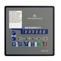
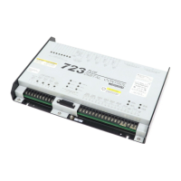
Overview of the DSLC-2 terminal layout and connections for various functions.
Visual representations of the DSLC-2 wiring for different systems and configurations.
Details on connecting the power supply to the DSLC-2 unit, including protective devices.
Instructions for connecting voltage measuring inputs for generator and busbar measurements.
Procedures and diagrams for connecting generator current transformers (CTs) for measurement.
Information on RS-485, RS-232, and Ethernet interfaces for communication and control.
Steps to install and use the Woodward ToolKit software for configuring the DSLC-2.
Detailed parameter settings and adjustments for the DSLC-2 synchronizer function.
Parameter settings for load control modes including droop, load sharing, and base load.
Parameter settings for the process control function, including PID adjustments.
Parameter settings for controlling reactive power and power factor of the generator.
Configuration of device network settings, segments, and password-protected access levels.
Setup and configuration of analog inputs and outputs for various control signals.
Settings for system rated frequency, generator voltage, PT/CT settings, and operating ranges.
Guidelines for initial setup and configuration of the DSLC-2 system.
Step-by-step procedures for adjusting speed and voltage bias outputs.
Procedure for setting up the load control droop for proper generator operation.
Steps to set up and verify the isochronous load sharing mode.
Instructions for setting up and tuning the DSLC-2 process control function.
Setup and adjustment procedures for the DSLC-2 var/PF control function.
Details the different operating modes of the synchronizer: Off, Run, Check, Permissive.
Explains the security checks and arbitration for dead bus closing operations.
Describes how the DSLC-2 matches generator voltage to the bus voltage for system efficiency.
Details how the synchronizer corrects frequency and phase for busbar lock.
Explains how to set up the generator to run at a slightly higher speed than the bus.
Automatic generator loading functions and mode switching based on contact inputs.
Setting control setpoints remotely via Ethernet or RS-485 interface.
| Type | Digital Synchronizer and Load Control |
|---|---|
| Power Supply | 24 VDC |
| Input Voltage Range | 18-32 VDC |
| Operating Temperature Range | -40°C to +70°C |
| Operating Modes | Isochronous, Droop |
| Communication | RS-485, Ethernet |
| Certifications | CE, UL |