DANGER - 230V:
ISOLATE THE MAINS ELECTRICITY
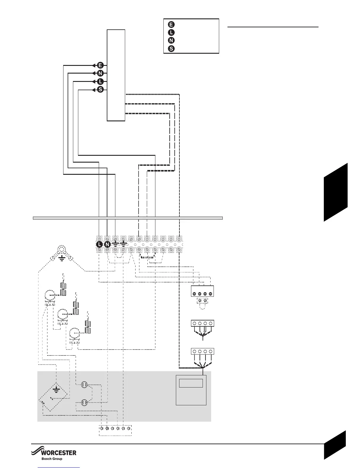
PRE-WIRED REMOTE 2 OR 3 PORT VALVE
CONTROL SET USING INTERNAL
PROGRAMMER:
Key to components:
O - REMOTE JUNCTION BOX (10-way) to
connect the following:
4Mains wiring 230V 50Hz.
4Hot water tank thermostat.
4Room thermostat.
4System water valves.
4Circulating pump.
P - 230V WORCESTER PROGRAMMER
(fitted into fascia panel).
F - INTERNAL PROGRAMMER CONNECTOR.
G- TERMINAL CONNECTOR BLOCK.
H - LINK CONNECTOR.
Remote (10 way) junction box (O)
requirements:
4The junction box (O) must be a terminal block
type, current rated to at least 5 amps.
4A 5 amp fuse must be fitted to the mains
supply.
4The junction box (O) must be fitted externally
to the boiler.
4Link 1 to 3 must be removed from the boiler
terminal connector block (G).
A frost thermostat can also be connected to the
remote junction box if required.
Internal Programmer (P) requirements:
2 and 3 port valve control sets:
4Set the pin on the rear of the programmer to
‘pumped’.
4Remove the link plug (H).
4Connect the plug from programmer (P) into
connector (F).
4Connect terminal 1 from the boiler terminal
block (G) to the ‘HOT WATER ON’ at the
remote junction box (O).
4C
onnect terminal 2 from the boiler terminal
bloc
k (G) to the ‘HEATING ON’ at the
remote junction box (O).
3 port valve control sets:
A 3 por
t valve control set also requires a live feed
from ‘
H
O
T
W
ATER OFF’ switch position.
4Remove the orange wire from terminal 9 and
pull back through the tie wraps. (Ensure that
the brown wire is firmly secured in terminal 9).
4C
onnect the orange wire to terminal 6 on the
boiler terminal block (G).
4Connect terminal 6 on the boiler terminal
bloc
k (
G
) to the ‘H
O
T W
ATER OFF’ at the
remote junction box (
O
).