Installation
6720813171 (2015/04)16
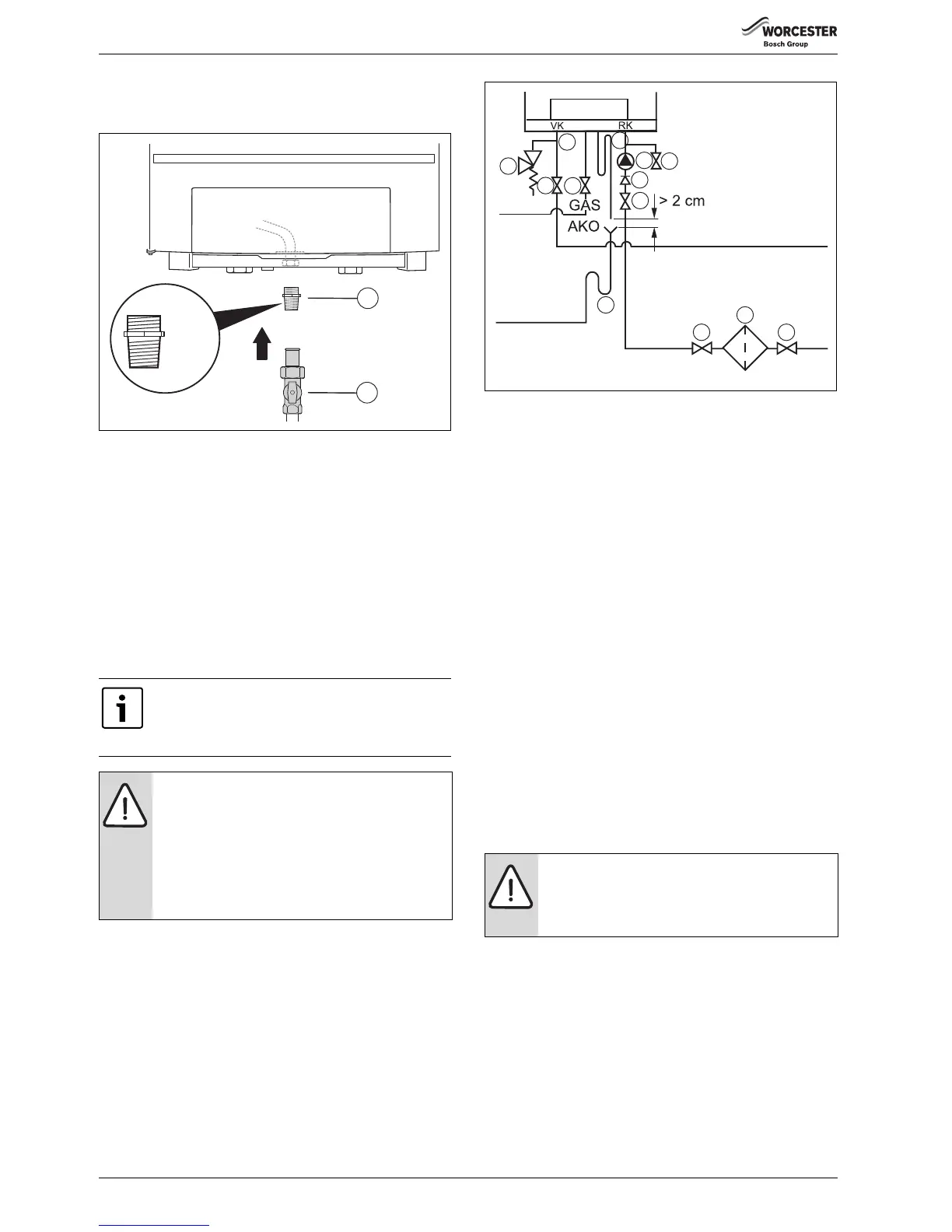
▶ Install the gas valve connector 1" [1] (accessory).
▶ Install the gas valve [2] onto the gas pipe. Use a gas valve with a
minimum diameter of 1".
Fig. 14 Making the gas connection
[1] Gas valve connector 1"
[2] Gas valve 1"
▶ Connect the main gas pipe to the gas connection making sure it is not
under stress. Use a gas pipe of at least Ø 22 mm.
▶ Make the gas connection according to the country-specific standards
and regulations.
▶ Carry out gas leak test on gas connection using leak detection spray
and purged as described in IGE/UP/1b.
Installing the heating flow and return pipe
The central heating system should be installed in accordance with
BS 6798 and, in addition, for small bore and micro bore systems,
BS 5449 or EN 12823.
▶ Connect the flow pipe with a flat rubber seal installed to the CHF
(CH boiler flow) connection [1] making sure it is not under stress.
Use a flow pipe with a minimum diameter of 1½".
▶ Connect the return pipe with a flat rubber seal installed to the CHR
(CH boiler return) connection [2] making sure it is not under stress.
Use a return pipe with a minimum diameter of 1½".
Fig. 15 Connecting the boiler flow and return
[1] CH boiler flow
[2] CH boiler return
[3] Isolating valves
[4] Drain cock
[5] Gas valve
[6] Pressure relief valve
[7] Condensate trap
[8] Pump
[9] Non-return valve
[10] Dirt filter
8.2.4 Installing the differential pressure controller
In situations where there is no low loss header, installing a bypass with a
differential pressure controller would not be required.
If a low loss header is present, it may be required -depending on the
situation - to install a bypass with a differential pressure controller to the
secondary side of the low loss header. This serves to protect the
secondary pump against overheating as a result of insufficient flow.
8.2.5 Installing the isolating valves
▶ Install a isolating valve for maintenance and repair purposes in both
the boiler flow and return circuits ( fig. 15, [3]). Use isolating
valves with a minimum diameter of 1½".
8.2.6 Installing the drain cock
▶ Connect a drain cock in the return circuit ( fig. 15, [4]).
8.2.7 Installing a pressure relief valve
▶ Install a 4-bar pressure relief valve ( fig. 15, [6]) with a minimum
passage of 22 mm in the flow circuit. Make sure that the pressure
relief valve is always installed between the boiler and the isolating
valve, so that the boiler will always be in contact with the pressure
relief valve, even if the isolating valves are closed.
8.2.8 Selecting and installing the pump
▶ Select a pump according to the hydraulic boiler resistance specified
in table 5 or in the curve in fig. 122 on page 62.
▶ When using the curve take the nominal required volume flow into
consideration according to table 3.
▶ When selecting the pump, take the maximum volume flow of the
boiler according to table 4 into consideration.
When using plastic pipes, observe the supplier’s
instructions - especially those referring to
recommended jointing techniques and the notes relating
to the heating system water on page 6
NOTICE:
To prevent contamination in the heating system we
recommend you to integrate a dirt filter [10] in the
return pipe, near the boiler. In an old system it is a
requirement to install a dirt filter.
▶ Install shut-off valves to enable filter cleaning
immediately upstream and downstream of the dirt
filter.
 Loading...


