Installation
6720813171 (2015/04) 19
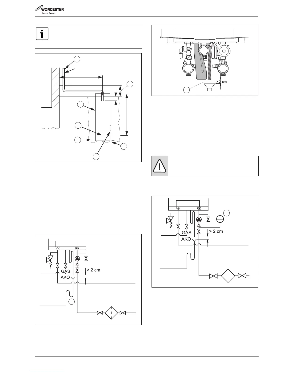
Fig. 22 External termination of condensate drain pipe to absorption
point
[1] External length of pipe 3 m max.
[2] Plastic tube
[3] Bottom of tube sealed
[4] Limestone chippings
[5] Two rows of three 12 mm holes at 25 mm centres, 50 mm from
bottom of tube and facing away from house
[6] Hole depth
[7] Ground (either/or)
8.2.11 Connecting the condensate drain pipe
▶ Connect the condensate drain pipe to the condensate trap
( fig. 23, [1] and fig. 24, [1]).
Fig. 23 Connecting the condensate trap
[1] Condensate trap
Fig. 24 Condensate drainage pipe
[1] Minimum distance > 2 cm
Observe the following regulations:
• The (local) waste water disposal regulations.
• The condensate trap in the connection kit must not be permanently
connected to the condensate drain pipe. The minimum distance
between the condensate trap and the condensate drain pipe is 2 cm.
An air gap should be maintained between the boiler condensate trap and
the condensate pipework.
8.2.12 Connecting the expansion vessel in a single-boiler system
▶ Connect the expansion tank to the boiler return (CHR). If a non-return
valve is available: connect the expansion vessel to the CH-side of the
non-return valve in the return circuit ( fig. 25, [1]).
Fig. 25 Connecting the expansion vessel in a single-boiler system
[1] Expansion vessel
When discharging condensate to an outside drain
caution must be taken to ensure blockage cannot occur
during freezing conditions. If this is likely to occur, the
use of a condensate trap is recommended.
 Loading...


