Commissioning
6720813171 (2015/04) 41
▶ Press and hold the “Chimney sweep” button [3] (approximately 2
seconds), until the dot in the right-hand bottom corner of the display
[9] appears. See also table 10, “Flue gas test”, page 34.
▶ After the “Burner” LED [6] has lit up wait for one minute until the
boiler is burning at full load.
▶ Measure the gas supply pressure and enter it in the commissioning
log book, page 72.
The gas supply pressure must be:
• for natural gas H min. 17 mbar, max. 25 mbar, nominal supply
pressure 20 mbar.
• for LPG min. 30 mbar, max. 50 mbar, nominal supply pressure
37 mbar.
▶ Press the “Service” button [4] repeatedly until the temperature
reading is shown in the display.
▶ Press the “Chimney sweep” button [3] to clear the reading. Also see
table 10, “Flue gas test”, page 50.
Fig. 86 BC10 basic controller
▶ Close the gas valve ( fig. 81, page 39).
▶ Remove the gauge-connection tube and tighten the screw plug on the
testing nipple again.
▶ Open the gas valve again by pushing on the gas valve and turning it ¼
rotation in an anticlockwise direction ( fig. 79, page 39).
10.2.7 Checking and adjusting the gas/air-ratio
▶ Open at least 2 thermostatic radiator valves. Do not switch on the
boiler.
▶ Push on the control panel to open it ( fig. 68, page 32).
▶ Switch off the heating system by pressing the mains switch of the
BC10 basic controller ( fig. 86, [1]).
▶ Close the gas valve ( fig. 81, page 39).
▶ Turn the vent key through a quarter rotation to undo the boiler door
lock ( fig. 71, see detailed picture, page 37).
▶ Push the fastener down and open the boiler door ( fig. 71,
page 37).
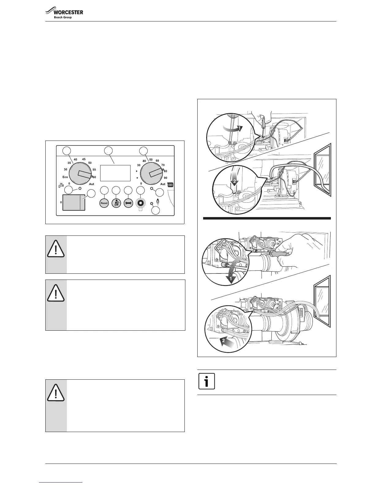
▶ Open the screw plug on the testing nipple for the burner pressure by
2 turns [1].
▶ Set the pressure gauge to “0”.
Fig. 87 Checking the gas/air ratio
▶ Use a connection tube to connect the positive port of the pressure
gauge to the testing nipple for burner pressure ( fig. 87, [2]).
▶ Slowly open the gas valve by pushing on the gas valve and turning it
¼ rotation in an anticlockwise direction ( fig. 79, page 39).
▶ Switch on the heating system by pressing the mains switch of the
BC10 basic controller ( fig. 86, [1]).
▶ Activate the Service mode in accordance with the “Service mode”
menu ( table 11, page 34).
DANGER: Danger of fatal accident from explosive
fumes.
▶ Check the testing nipples used for leaks.
▶ Only use approved leak detection spray to locate
leaks.
NOTICE:
▶ Check the gas supply pipe or contact the relevant gas
utility company if the required supply pressure is not
available.
▶ If the supply pressure is too high, a gas pressure
regulator must be integrated upstream of the gas
fitting. Contact the gas utility company.
WARNING:
Damage to the boiler by incorrect adjustment of the gas/
air-ratio.
▶ Adjust gas/air-ratio only with part load.
▶ Adjust gas/air-ratio only based on the gas/air
pressure differential and never based on measured
flue gas values such as CO/CO
2
/NO
x
.
 Loading...


