Installation
6720813171 (2015/04) 21
If this could occur the appliance must be turned off, and labelled as
unsafe until corrective action can be taken.
8.3.2 Air supply and flue gas exhaust in a room sealed installation
A ventilation cover is integrated into the condensing gas system boilers.
This cover houses a number of components, such as the burner and the
heat exchanger. Since this ventilation cover is part of the air supply
system, it is vital that it is always installed correctly.
To ensure optimal operation, the appliances must be connected to a
Worcester horizontal or vertical flue terminal. These terminals have been
developed specifically for Worcester condensing gas boilers and have
been comprehensively tested for trouble free operation when correctly
installed.
Standard horizontal flue pack ( fig. 27) for GB162-80/100:
• 1: Flue turret 100/150;
• 2: Horizontal flue terminal 100/150;
• 3: Flue finishing kit.
Standard horizontal flue pack ( fig. 27) for GB162-50/65:
• 1: Flue turret 80/125;
• 2: Horizontal flue terminal 80/125;
• 3: Flue finishing kit.
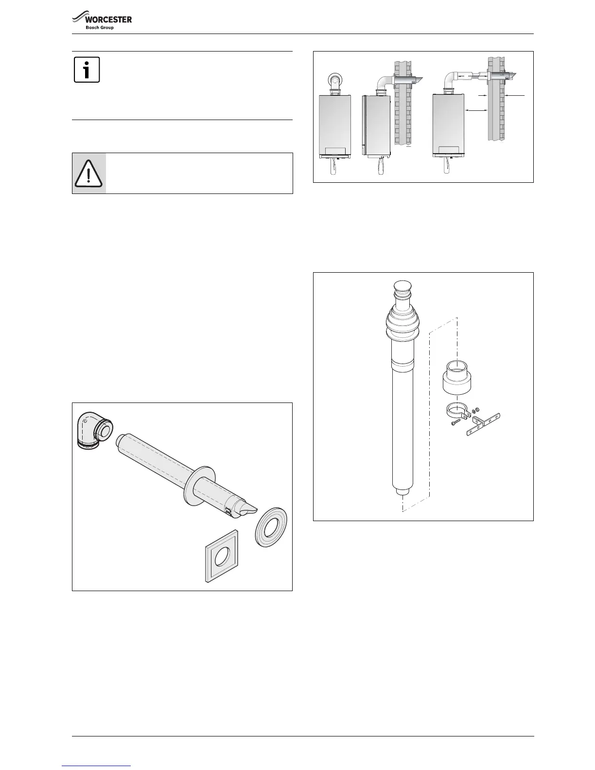
Fig. 27 Standard horizontal flue pack
Fig. 28 Side flue and rear flue installation
Standard vertical flue pack ( fig. 29) for GB162-80/100:
• Concentric vertical flue pipe 100/150;
• Wall clamp.
Standard vertical flue pack ( fig. 29) for GB162-50/65:
• Concentric vertical flue pipe 80/125;
• Wall clamp.
Fig. 29 Standard vertical flue pack
It is very important to ensure, that products of
combustion discharging from the terminal cannot re-
enter the building or any other adjacent building.
Through ventilators, windows, doors, other sources of
natural air infiltration, or forced ventilation/air-
conditioning.
DANGER:
▶ Only use Worcester flue gas systems. As other flue
gas systems are not tested with this appliance.
 Loading...


