Operation
6720813171 (2015/04)32
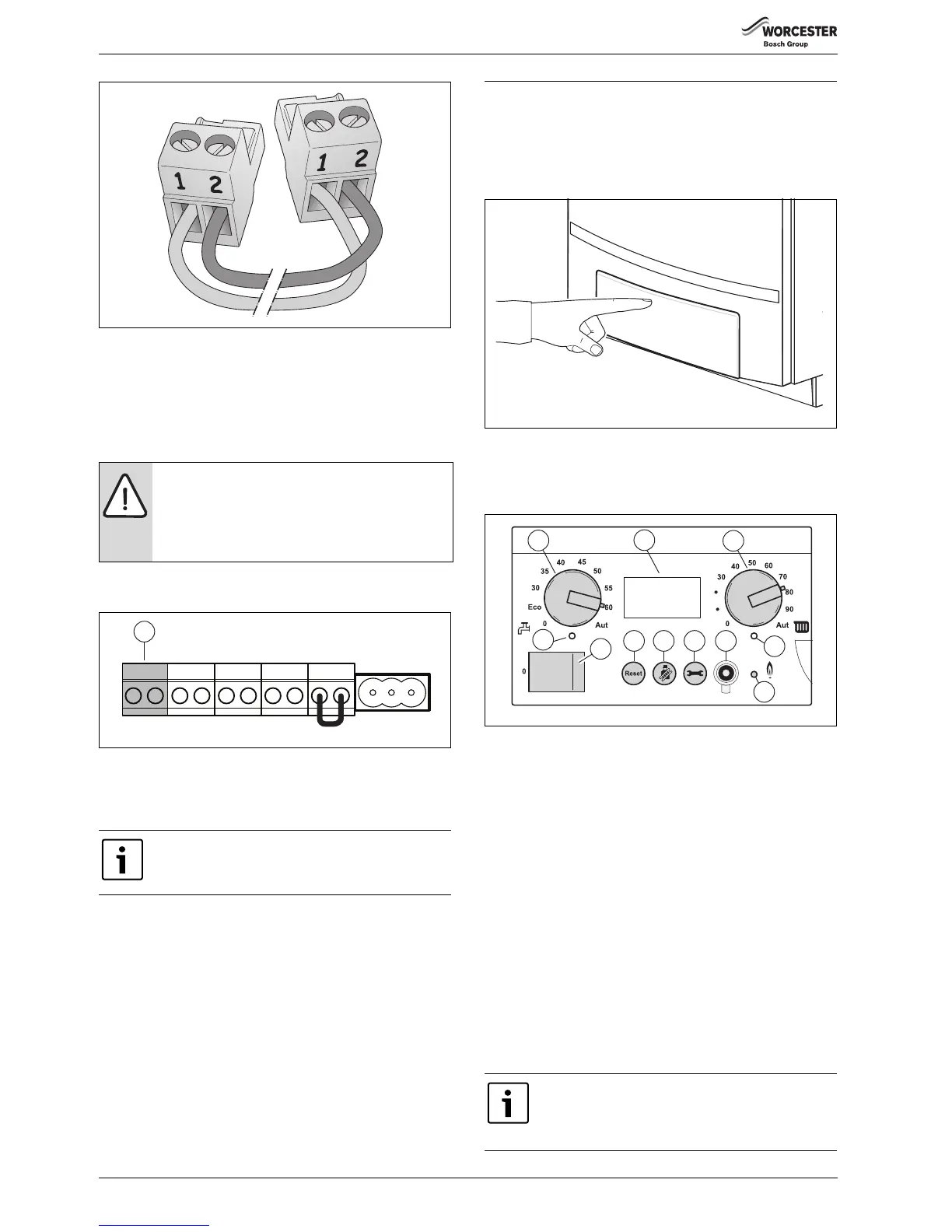
Fig. 66 EMS bus polarity
Installing and connecting function modules outside the boiler
▶ Install the module on the wall.
▶ Make a sufficiently long EMS bus connection cable, using a 2-core
cable of 0.4 - 0.75 mm² and the connector enclosed with the module
( fig. 66). Important: Use the connector of the same colour as the
connections on the module.
▶ Connect the EMS bus connection cable to the orange connection of
the terminal strip [1].
Fig. 67 Terminal strip - Room controller RC and EMS bus (connection
colour orange)
▶ Connect the other end of the EMS bus connection cable to the first
module ( fig. 65).
▶ If more modules are used, the EMS bus connection for the second
module may be branched off from the first module using the cable
enclosed with the module.
▶ Connect the EMS bus connection lead of the first module to the next
module ( fig. 65).
▶ Make a sufficiently long 230 VAC mains cable, using a 3-core cable of
at least 0.75 mm² with an earthing wire, the connector enclosed with
the module and a 230 VAC earthed plug.
▶ Connect the 230 VAC mains cable to the module ( fig. 65). If more
modules are used, the 230 VAC supply to the next module can be
branched off from the previous module using the connector enclosed
with the module and a 3-core 0.75-mm² current cable with an
earthing wire.
▶ Connect the 230 VAC supply cable of the previous module to the
next module ( fig. 65).
9Operation
9.1 General items
The boiler is fitted with a control unit, the BC10 basic controller.
This controller can be used to control the heating system.
▶ Push on the control panel to open it.
Fig. 68 Opening the control panel
The BC10 basic controller is located on the left, behind the door
( fig. 1, [4]).
The BC10 basic controller consists of the following components:
Fig. 69 BC10 basic controller
[1] Mains switch
[2] “Reset” button
[3] “Chimney sweep” button
[4] “Service button”
[5] Service Connector
[6] “Burner” LED (On/Off)
[7] “Heat demand” LED
[8] Maximum CH flow temperature dial
[9] Display
[10] DHW temperature dial
[11] “DHW mode” LED
Mains switch
The mains switch [1] is used to switch the boiler on and off.
“Reset” button
If a fault has occurred you may have to restart the boiler by pressing the
“Reset” button [2]. This is only required in the event of a “locking” fault.
“Blocking” faults are reset automatically as soon as their cause has been
corrected. The display shows [\/r/e| during the reset operation.
NOTICE:
Pay attention to the polarity when using an EMS bus
connection cable.
▶ Connect the wire from terminal 1 to terminal 1 and
from terminal 2 to terminal 2 ( fig. 65 and 66).
The module may have the letters RC or EMS above the
connection ( fig. 65, [1]).
 Loading...


