Key to symbols and safety instructions
6720813171 (2015/04) 5
12.3 Carry out a visual check for general signs of
corrosion . . . . . . . . . . . . . . . . . . . . . . . . . . . . . . . . . . . . .47
12.4 Gas valve leakage test . . . . . . . . . . . . . . . . . . . . . . . . . . 47
12.5 Measuring the ionisation current . . . . . . . . . . . . . . . . . 47
12.6 Measuring the gas inlet pressure (working pressure) . 47
12.7 Checking and adjusting the gas/air-ratio . . . . . . . . . . . 47
12.8 Carrying out a leakage test in operating conditions . . . 47
12.9 Measuring the flue gases CO
2
emissions . . . . . . . . . . . 47
12.10 Filling the heating system . . . . . . . . . . . . . . . . . . . . . . . 47
12.11 Checking the flue gas connection . . . . . . . . . . . . . . . . . 47
12.12 Inspection log book . . . . . . . . . . . . . . . . . . . . . . . . . . . . 48
13 Maintenance . . . . . . . . . . . . . . . . . . . . . . . . . . . . . . . . . . . . . . . . 48
13.1 Removing the boiler door . . . . . . . . . . . . . . . . . . . . . . . 48
13.2 Cleaning the heat exchanger, burner and
condensate trap . . . . . . . . . . . . . . . . . . . . . . . . . . . . . . .49
13.2.1 Removing the gas valve . . . . . . . . . . . . . . . . . . . . . . . . . 49
13.2.2 Removing the burner cover with the fan and the
gas valve . . . . . . . . . . . . . . . . . . . . . . . . . . . . . . . . . . . . .49
13.2.3 Removing the burner and the burner seal . . . . . . . . . . 50
13.2.4 Checking ignition unit . . . . . . . . . . . . . . . . . . . . . . . . . . 50
13.2.5 Disconnecting the condensate trap . . . . . . . . . . . . . . . 51
13.2.6 Removing the condensate collector . . . . . . . . . . . . . . . 51
13.2.7 Cleaning the heat exchanger . . . . . . . . . . . . . . . . . . . . . 52
13.3 Checking and adjusting the gas/air-ratio . . . . . . . . . . . 52
13.4 Function check in operating conditions . . . . . . . . . . . . 52
13.5 Service record log book . . . . . . . . . . . . . . . . . . . . . . . . 52
14 Display information . . . . . . . . . . . . . . . . . . . . . . . . . . . . . . . . . . 53
14.1 Removing the control panel from the boiler . . . . . . . . . 53
14.2 Display readings . . . . . . . . . . . . . . . . . . . . . . . . . . . . . . 53
14.3 BC10 Display settings . . . . . . . . . . . . . . . . . . . . . . . . . . 54
14.4 BC10 Display codes . . . . . . . . . . . . . . . . . . . . . . . . . . . 54
14.5 Re-fit the control panel in the boiler . . . . . . . . . . . . . . . 60
15 Technical specifications . . . . . . . . . . . . . . . . . . . . . . . . . . . . . . 61
15.1 Spare parts list GB162-80/100 . . . . . . . . . . . . . . . . . . 63
15.2 Spare parts list GB162-50/65 . . . . . . . . . . . . . . . . . . . 66
1 Key to symbols and safety instructions
1.1 Key to symbols
Warnings
Keywords indicate the seriousness of the hazard in terms of the
consequences of not following the safety instructions.
• NOTICE indicates that material damage may occur.
• CAUTION indicates that minor to medium injury may occur.
• WARNING indicates that serious injury may occur.
• DANGER indicates possible risk to life.
Important information
Additional symbols
PLEASE READ THESE INSTRUCTIONS CAREFULLY BEFORE
STARTING INSTALLATION.
THESE INSTRUCTIONS ARE APPLICABLE TO THE WORCESTER
APPLIANCE MODEL(S) STATED ON THE FRONT COVER OF THIS
MANUAL ONLY AND MUST NOT BE USED WITH ANY OTHER MAKE OR
MODEL OF APPLIANCE.
THE INSTRUCTIONS APPLY IN THE UK AND IRELAND ONLY AND MUST
BE FOLLOWED EXCEPT FOR ANY STATUTORY OBLIGATION.THIS
APPLIANCE MUST BE INSTALLED BY A GAS SAFE REGISTERED,
COMPETENT PERSON. FAILURE TO INSTALL CORRECTLY COULD LEAD
TO PROSECUTION.
IF YOU ARE IN ANY DOUBT CONTACT THE WORCESTER TECHNICAL
HELPLINE (0330 123 3366).
DISTANCE LEARNING AND TRAINING COURSES ARE AVAILABLE FROM
WORCESTER.
PLEASE LEAVE THESE INSTRUCTIONS WITH THE COMPLETED
INSTALLATION CHECKLIST, (OR A CERTIFICATE CONFIRMING
COMPLIANCE WITH IS 813, EIRE ONLY) AND THE USER MANUAL WITH
THE OWNER OR AT THE GAS METER AFTER INSTALLATION OR
SERVICING.
THE INSTALLATION CHECKLIST CAN BE FOUND IN THE BACK PAGES
OF THIS INSTALLATION MANUAL.
ABBREVIATIONS USED IN THIS MANUAL:
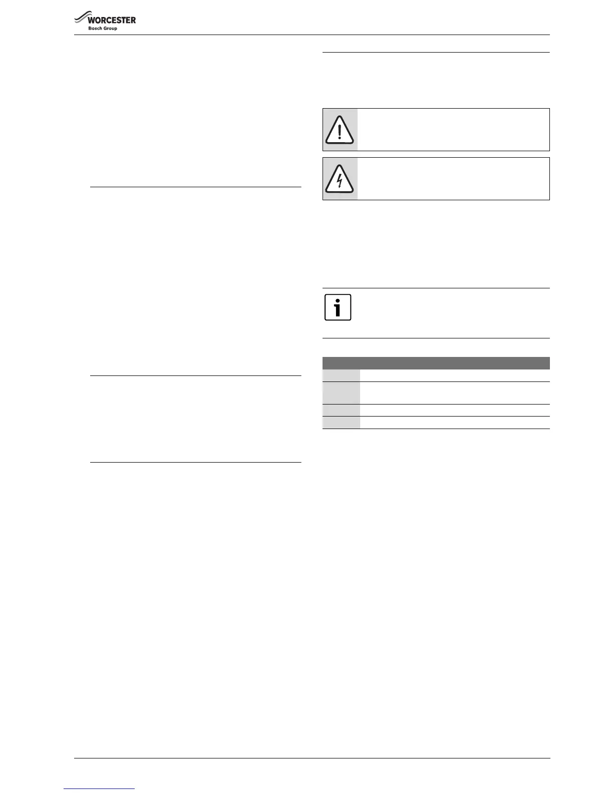
Warnings in this document are framed and identified by
a warning triangle which is printed on a grey
background.
Electrical hazards are identified by a lightning symbol
surrounded by a warning triangle.
Important information in cases where there is no risk of
personal injury or material losses is identified by the
symbol shown on the left. It is bordered by horizontal
lines above and below the text.
Symbol Meaning
▶ a step in an action sequence
a reference to a related part in the document or to other
related documents
• a list entry
– a list entry (second level)
Table 1
 Loading...


