Commissioning
6720813171 (2015/04)42
▶ Set the capacity to minimum (part load) according to the “Service
mode” menu ( table 11, page 34).
▶ After the “Burner” LED ( fig. 86, [6]) has lit up wait for one minute
until the boiler is burning at part load.
▶ Read the differential pressure during service mode. The differential
pressure (p
gas
- p
air
) must be –5 Pa (±5 Pa) (indication on the
pressure gauge: –10 to 0 Pa).
Fig. 88 Gas/air difference at low load
▶ Enter the result in the commissioning log book ( section 10.5
“Commissioning record log book”, page 45).
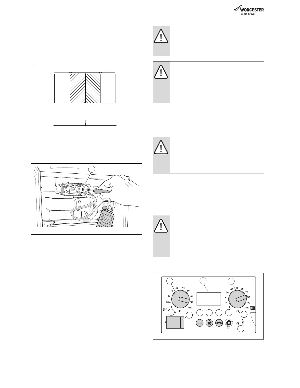
▶ If the gas/air-ratio is incorrect, it must be adjusted on the set screw
(Torx 40 H) [1]. The set screw is located behind the screw-on cover.
Fig. 89 Gas/air difference at low load
▶ Press the “Chimney sweep” button ( fig. 86, [3]) until the dot
disappears from the display.
▶ Switch off the heating system by pressing the mains switch of the
BC10 basic controller ( fig. 90, [1]).
▶ Close the gas valve ( fig. 81, page 39).
▶ Remove the measuring devices.
▶ Tighten the screw in the burner pressure measuring nipple.
▶ Slowly open the gas valve by pushing on the gas valve and turning it
¼ rotation in an anticlockwise direction ( fig. 79, page 39).
▶ Switch on the heating system by pressing the mains switch of the
BC10 basic controller ( fig. 90, [1]).
▶ Press and hold the “Chimney sweep” button ( fig. 90, [3])
(approximately 2 seconds), until the dot in the right-hand bottom
corner of the display ( fig. 90, [9]) appears. See also table 10,
“Flue gas test”, page 34.
▶ After the “Burner” LED ( fig. 90, [6]) has lit up wait for one minute
until the boiler is burning at full load.
▶ Press the “Chimney sweep” button ( fig. 90, [3]) to clear the
reading. See also table 10, “Flue gas test”, page 34.
▶ Check that the boiler performance is still at the required value. See
table 13 “Settings”, page 36.
10.2.8 Carrying out a leakage test in operating conditions
▶ Press and hold the “Chimney sweep” button [3] (approximately 2
seconds), until the dot in the right-hand bottom corner of the display
[9] appears. See also table 10, “Flue gas test”, page 34.
▶ After the “Burner” LED [6] has lit up wait for one minute until the
boiler is burning at full load.
▶ Use a foaming product to check all sealing locations in the total gas
circuit of the burner while the burner is active.
▶ Press the “Chimney sweep” button [3] to clear the reading. See also
table 10, “Flue gas test”, page 34.
Fig. 90 BC10 basic controller
DANGER: Danger of fatal accident from explosive
fumes.
▶ Check the testing nipples used for gas tightness.
▶ Only use approved leak detection products to locate
leaks.
WARNING:
Damage to the installation due to short circuits.
▶ Cover any hazardous locations prior to locating the
leaks.
▶ Do not spray the leak detection product on cable
runs, plugs or electrical wiring. Do not let it drip onto
them either.
DANGER: Danger of fatal accident from explosive
fumes.
Pipes and fittings may leak after commissioning
activities have been carried out.
▶ Only use approved leak detection products to locate
leaks.
WARNING:
Damage to the installation due to short circuits.
▶ Cover any hazardous locations prior to locating the
leaks.
▶ Do not spray the leak detection product on cable
runs, plugs or electrical wiring. Do not let it drip onto
them either.
 Loading...


