Commissioning
6720813171 (2015/04) 37
10 Commissioning
This section explains how to start up the boiler.
▶ Complete the commissioning record log book after carrying out the
activities described below ( section 10.5 “Commissioning record
log book”, page 45).
10.1 Filling the heating system
10.1.1 Filling the heating system
The pre-pressure of the expansion vessel must be at least equal to the
static pressure (system height to the centre of the expansion vessel),
however never less than 0.5 bar.
▶ Push on the control panel to open it ( fig. 68).
▶ Turn the maximum CH flow temperature dial [8] and DHW
temperature dial [10] anticlockwise to the “0” position.
Fig. 70 BC10 basic controller
▶ Turn the vent key through a quarter rotation [1] to undo the boiler
door lock ( detailed picture).
▶ Push the fastener down [2] and open the boiler door [3].
▶ Remove the insulation cover of the pump group [4].
Fig. 71 Opening the boiler door
The boiler has an automatic air vent to purge the boiler.
To purge the boiler, every radiator in the heating system must have a
purge facility. In some situations it may even be necessary to provide
extra purging facilities at certain locations.
▶ Turn the cap of the automatic air vent through one rotation to loosen
it.
Fig. 72 Opening the automatic air purging unit
Filling and refilling of the heating circuit must have been carried out by a
method that has been approved by the Water Regulation Advisory
Scheme (WRAS), for the type of heating appliances, i.e. Domestic
(in-house) Fluid Category 3. Non-Domestic (other than in-house) Fluid
Category 4. Depending on the Fluid Category the approved method
should comprise of the following:
Requirements Fluid Category 3 systems
• Control valve (stop valve) including a double check valve on the
mains cold water supply pipe.
• Temporary connection to be removed after filling (filling loop).
• Control valve (stop valve) on the heating system pipework.
Fig. 73 System fill - category 3
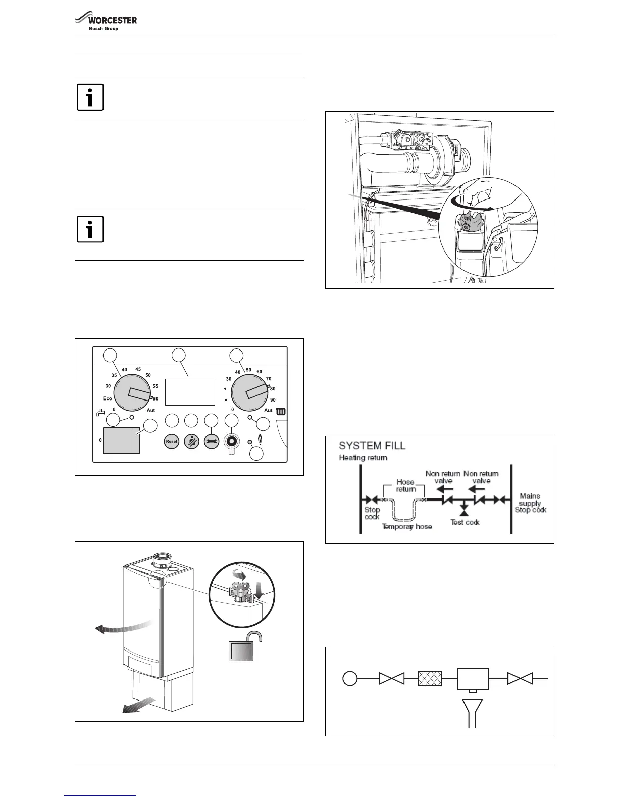
Requirements Fluid Category 4 systems
• Control valve (stop valve) on the mains cold water supply pipe.
•Strainer.
• Water non-return valve with reduced pressure Zone (RPZ valve
assembly) incorporating a Type BA air gap.
•Tundish.
• Control valve (stop valve) on the heating system pipework.
Fig. 74 System fill - category 4
If a fault occurs, then refer to the servicing manual or
contact Worcester.
At initial start up, the boiler will start up as soon as the
system pressure exceeds 1.0 bar. If the system pressure
falls to below 0.2 bar the boiler will stop and generate a
fault code.
 Loading...


