Installation
6720813171 (2015/04) 29
▶ Connect the black pre-wired main appliance lead to a permanent live
supply (from the same fused isolator as all other controls on the
heating system), L N E.
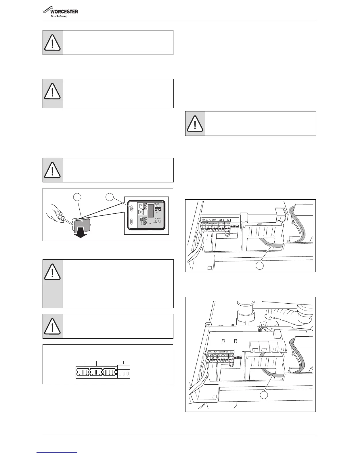
▶ Remove the grey cover of the 230 Volt converter [1].
▶ Feed the 230 V switch live and neutral (from external controls)
through the cable gland.
▶ Identify the 230 V terminal block by the hashed area and 230 VAC
warning triangle.
▶ Connect the switch live to terminal “1” and a neutral to terminal “2”
[2].
Fig. 52 Connection box - 230 Volt connection
8.5.5 230 V connections (only for GB162-50/65)
Fig. 53 Terminal strip - external heating pump 230 V (connection
colour green)
Connecting an external boiler pump - general
Since the boiler has not been fitted with a pump, a pump must be
connected to the boiler.
When using a pump group with an integrated pump:
▶ Read the assembly instructions of the pump group for the electrical
pump connections.
If you do not make use of a pump group, you can connect the external
pump in 2 ways:
• to the unused 230 VAC pre-wired pump cable;
• to the green PK terminal of the boiler. To connect order a PK plug
(accessory).
Proceed as follows:
The maximum electrical load that can be connected to the free 230 VAC
connection cable of the pump ( fig. 54, [1]) and to the green EP
connector ( fig. 56) is 250 Watts in total. If a load of more than
250 Watts is to be connected, this is possible by using an additional
230/230 V relay, which has to be installed by a registered installer/
electrician.
Connection to the free 230 VAC connection lead
▶ Unwind the 230 VAC cable [1] and route it out of the boiler
( fig. 55).
Fig. 54 230 VAC cable of the pump
▶ Cut the plug from the 230 VAC cable.
▶ Connect the 230 VAC cable to the pump.
Fig. 55 Route the 230 VAC pump cable
WARNING:
▶ This appliance must be earthed.
NOTICE:
▶ Connect the 230 Volt converter (grey box) via the
pair of black low voltage cable to terminal WA.
( figure 48).
NOTICE:
▶ Terminal 3 [2] is not used.
NOTICE:
The 230 V connections can only be used with a
corresponding control unit. If you use other than the
GB162 pump group, you must ensure that it correctly
connects to the terminal strip in fig. 53.
▶ Observe the layout document and the installation
instructions of the control unit.
WARNING:
▶ Do not connect a temperature controller to the 230 V
connections.
 Loading...


