Installation
6720813171 (2015/04) 27
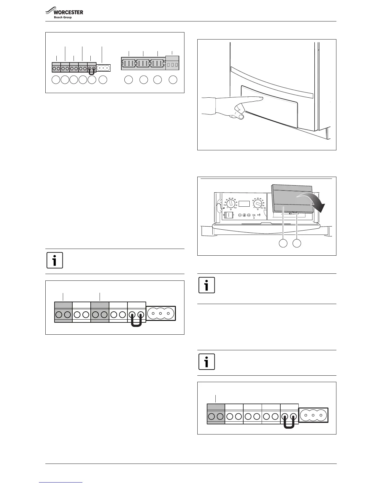
Fig. 42 Terminal strip connections
[1] Room controller RC and EMS bus (connection colour orange)
[2] Outdoor-temperature sensor (connection colour blue)
[3] Connection terminal for potential free heat demand (connection
colour green)
[4] DHW temperature sensor (connection colour grey)
[5] External switch contact, potential free, e. g. for floor heating
(connection colour red) (thermal protection)
[6] Connection for external three-way valve
[7] External heating pump 230 V (connection colour green) (for use
with non Worcester pump group)
[8] DHW pump 230 V (connection colour grey)
[9] DHW Circulation pump 230 V (connection colour lilac)
[10] Mains connection 230 V AC (connection colour white)
General control connection
The following controls can be connected to the boiler.
• Control with contact for potential free heat demand
• RC25, RC35 room controller
• 4121, 4122, 4323 cascade controller
• Error reporting module EM10, 0 – 10 V input (can be used to convert
a 0 – 10 V signal to a modulating signal).
Connecting and installing a modulating control (room controller)
Fig. 43 Terminal strip – RC room controller and WA potential-free heat
demand
Installing an RC35 room controller as an outdoor temperature-
dependant control in the boiler
For outdoor temperature-dependant control operation only: it is
possible to install the room controller (e.g. RC35) in the boiler. In this
case, the controller does not have to be connected to the terminal strip
afterwards. If you would like to use this room controller for room
temperature-controlled operation, the room controller must be installed
in a living room.
▶ Push the arrow on the control panel cover to open ( fig. 44).
Fig. 44 Opening the control panel
▶ Remove the cover [1].
▶ Install the RC35 in the slot [2].
Fig. 45 Remove the cover and install the room controller in the boiler
(only for outdoor temperature-dependant operation)
Installing and connecting other controllers outside the boiler
▶ Install the controller as described in the relevant installation
instructions.
▶ Connect a RC25 or RC35 room controller or a 4121, 4122 or 4323
cascade controller to the orange RC terminal using a 2-core cable of
0.75 mm².
Fig. 46 Terminal strip – Room controller RC and EMS bus (connection
colour orange)
It is not possible to connect more than one room
controller ( fig. 43).
 Loading...


