OIL SUPPLY
INSTALLATION & SERVICING INSTRUCTIONS FOR GREENSTAR HEATSLAVE II EXTERNAL 12/18-18/25-25/32
6 720 805 210-01
11
PRE -
INSTALLATION
OIL SUPPLY
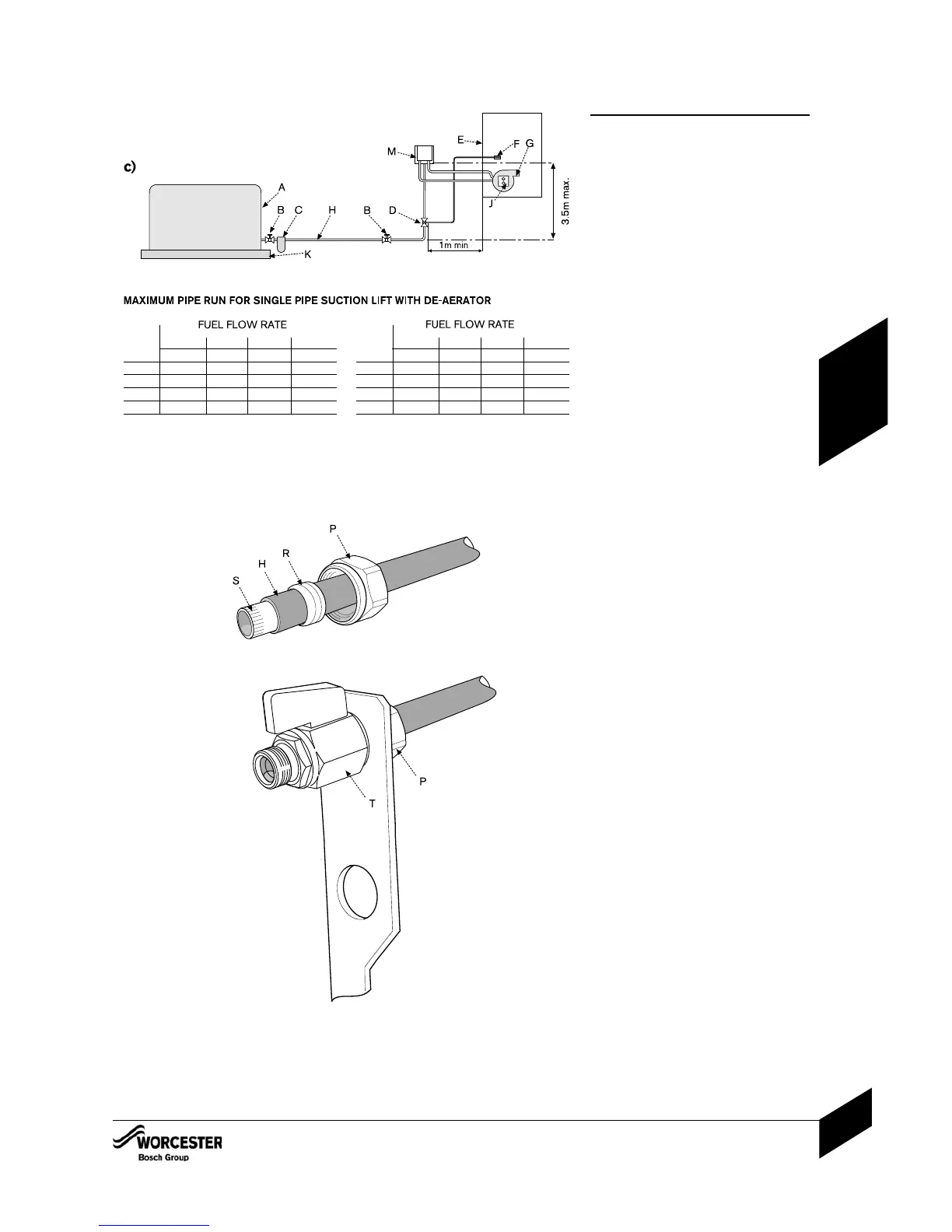
c) Single pipe suction lift with de-aerator
Maximum suction height 3.5 metres. The oil
tank (A) must be positioned below the oil pump
(J). Create an inlet and return loop between the
de-aerator (M) and oil pump (J).
A non-return valve must be incorporated within
the de-aerator or fitted to the oil line between
the oil storage tank (A) and the de-aerator (M).
A top feed oil tank fitted with a de-aerator
using an internal non-return valve should have
any non-return valves fitted in the base of the
tank to the suction line removed to assist
purging air from the oil line.
Pipework
4 Use copper pipe of the correct diameter
according to the information shown opposite.
• If using soft copper pipe (R220) with a
compression fitting, an insert must be used
to prevent the pipe from collapsing or
distorting when the fitting is tightened.
4 Slide nut (P) and olive (R) onto the oil
supply pipe (H).
4 Slide insert (S) into the pipe.
4 Offer the pipe to the fitting (T) and tighten the
nut (P).
4 Use flexible hoses to connect to the oil pump (J).
4 Lay the oil supply pipe (H) as straight and
level as possible to avoid air pockets and
unnecessary friction losses. Route away
from the boiler access door or other hot
surfaces.
4 Install a manual isolating valve (B) to the oil
supply pipe (H), as close to the oil storage
tank (A) as possible.
4 Fit an oil strainer and water separator (C) to
the oil supply pipe, near the oil storage tank.
Fit an additional oil filter (N, 70μm max
filtration size with the filter element to be of
the disposable media (paper) type) close to
the boiler, but not inside the boiler casing.
4 Fit a fire valve in accordance with BS 5410.
The fire valve (D) should be fitted externally
to the building with the fire valve sensor (F)
located within the appliance case using the
clip located under the right hand side of the
cross brace at the top of the boiler.
A fire valve with a shut off temperature of
85°C or higher must be fitted to avoid
the possibility of nuisance shut offs.
A capillary type valve provides a neat and
simple installation. Alternatively, a fusible
link or electrical system may be used.
Under no circumstances should a
combination isolating/fire valve be used
as the sole fire protection device.
HEAD 2.5kg/h 5kg/h 10kg/h 10kg/h
8mmØ 8mmØ 8mmØ 10mmØ
0 100 55 26 100
0.5 95 45 23 100
1.0 80 40 20 90
1.5 70 35 17 75
HEAD 2.5kg/h 5kg/h 10kg/h 10kg/h
8mmØ 8mmØ 8mmØ 10mmØ
2.0 60 30 14 65
2.5 45 25 11 50
3.0 35 15 8 35
3.5 25 10 5 20
The table and illustration above is a guide only and does not in any way override the
de-aerator manufacturers instructions.

 Loading...


