FAULT FINDING & DIAGNOSIS
INFORMATION MENU
INSTALLATION & SERVICING INSTRUCTIONS FOR GREENSTAR HEATSLAVE II EXTERNAL 12/18-18/25-25/32
6 720 805 210-01
53
FAULT FI NDI NG
& DIAGNOSIS
FAULT FINDING & DIAGNOSIS
INFORMATION MENU
1
2
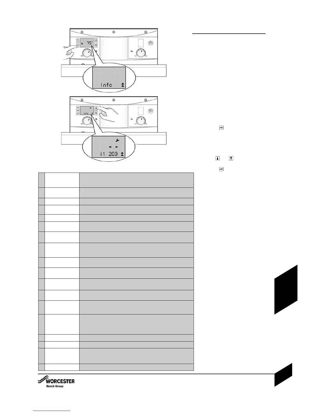
Selecting the Information Menu:
The Information Menu is a ‘read only’ menu.
Information about the boiler is displayed here,
some of the values are updated in real time to
give the current status of the boiler.
All menus time-out after 2 minutes and the
display returns to the normal operation display,
the display backlight turns off after another 30
seconds and goes into stand-by mode.
Double up or down arrows indicate that the
menu can only be scrolled up or down, an up
arrow combination indicates osition in the menu
where options can be scrolled either up or
down.
To enter the Information Menu:
14 Press the button to enter the
Information Menu.
l A 3 figure boiler status code will be
displayed alongside the Information Menu
number. Refer to page 39 for a desription
of the boiler status codes.
24 Use the and arrow buttons to
scroll through the menu items.
34 Press the button again to exit the
Information Menu.
i1 Current status Every operation and mode of the boiler has a related boiler status code.
The boiler status code is displayed on the screen as a 3 figure number.
Refer to page 39 or error table for information on the boiler status code.
i2 Last error This can be viewed during normal operation.
Displays tha last diagnostic code with boiler status code.
i3 Maximum CH output
The maximum possible CH output is displayed in kW.
i4 Maximum DHW
output
The maximum possible DHW output is displayed in kW.
i6 DHW flow rate
The screen displays the current DHW flow rate in 0.1l/m units.
i7 CH flow temperature
set point
This is the temperature set point for the primary flow from the main heat
exchanger. This will be zero during HW demand.
i9 Flow temperature
This is the actual temperature from the main heat exchanger displayed
in real time (rounded to 0.5°C units).
i10 Maximal temperature
This is the current temperature from the ‘maximal safety sensor’
displayed in real time (rounded to 0.5°C units).
The sensor is mounted on the top of the primary heat exchanger.
i11 DHW flow
temperature
Current DHW flow temperature displayed in real time (rounded to 0.5°C
units).
i12
DHW temperature
setpoint
This is the thermal store temperature, selected via the Hot Water control
knob on the fascia, displayed in real time (rounded to 0.5°C units).
i13
Thermal store
current temperature
This is the thermal store current temperature (rounded to 0.5°C units).
i14
DCW inlet
temperature
Current DCW inlet temperature displayed in real time (rounded to 0.5°C
units).
i15
Out door
temperature
This is the out door temperature displayed in real time (rounded to 0.5°C
units). Only available if a Weather Compensation sensor has been fitted
and Weather Compensation is active.
i19
Time inputs This indicates the status of the optional fascia mounted controls:
0 = CH off, DHW off
1 = CH off, DHW on
2 = CH on, DHW off
3 = CH on, DHW on
i20
Software version CBS software version of main PCB.
i21 Software version HIS software version of the HIS PCB.
i22
HCM number
HCM last 3 digits displayed:
391 = 12/18kW
390 = 18/25kW
301 = 25/32kW
i23
HCM version number For example ‘4’
Information Menu listing:

 Loading...


