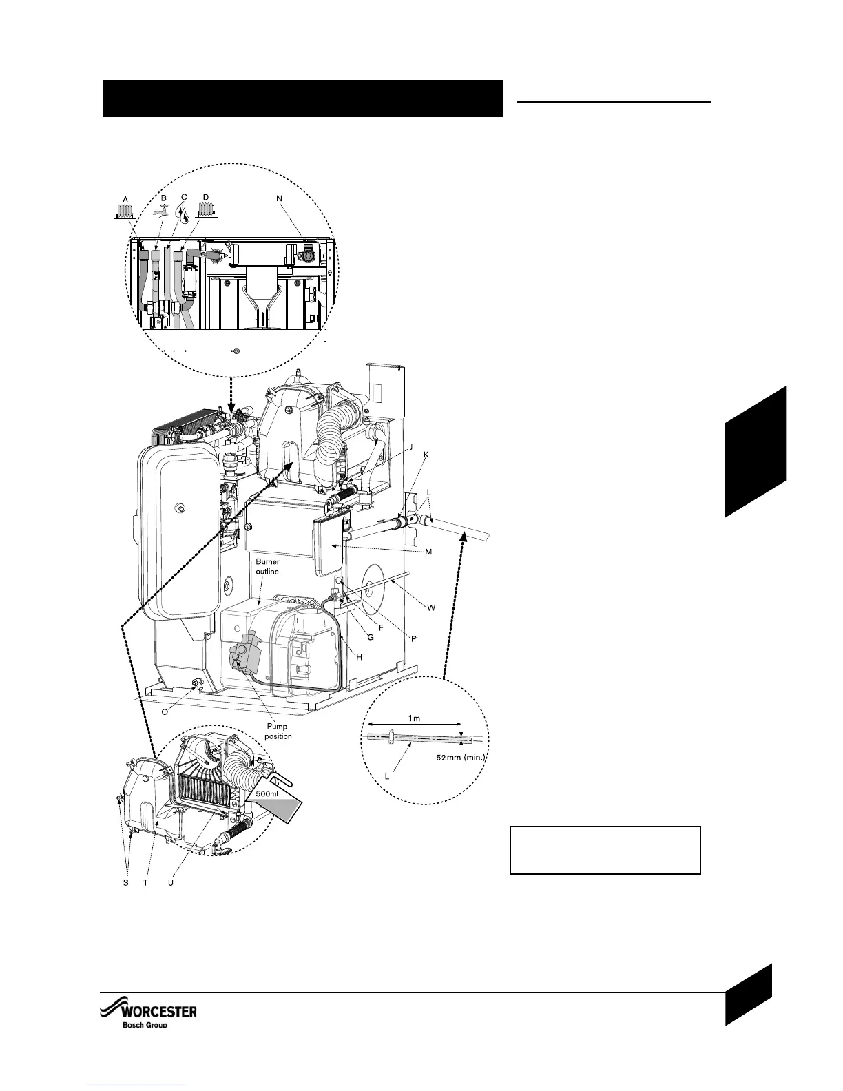
PIPEWORK CONNECTIONS
A - CH flow 22mmØ copper (28mmØ on
25/32 models)
B - DHW flow 22mmØ
C - DHW water main inlet 15mmØ
D - CH return 22mmØ copper (28mmØ on
25/32 models)
F - 10mmØ oil supply connection
G - Oil isolating valve (10mmØ)
H - Flexible oil hose*
J - Flue manifold condensate outlet
K - Condensate outlet and flexible push fit
connect (21.5mmØ) - supplied
L - Condensate pipe - not supplied
M - Condensate trap -
supplied
N - Pressure relief (15mmØ)
O- Drain
P - Fixing point for optional return oil pipe
WATER CONNECTIONS:
4Ensure all pipework is clean.
NOTE: That surplus water may be present
due to factory testing.
4Align water pipework and connect.
4Check that all unused sockets have been
capped.
OIL SUPPLY CONNECTIONS:
4Route the oil supply pipe (W) along either side
of the boiler as required and connect to the
isolating valve (G) and ensure the valve is
closed.
*NOTE: Replace flexible hose at annual
service to prevent possible oil
leakage.
4Connect the flexible oil hose (H) to the
isolating valve (G).
CONDENSATE CONNECTION:
4Connect 21.5mm polypropylene pipe (L) (not
supplied) to the condensate waste pipe
flexible push fit connector (K) and terminate to
waste.
4Do not use any solvents, adhesives or
lubricants when pushing the pipe into the
rubber connector (K).
4Ensure that the condensate pipe runs away
from the boiler at a constant fall of 52mm
(min.) for every metre.
4Seal all condensate pipe joints.
4Carefully pour 500ml of water into the
condensate collection (U) to fill condensate trap.
4Check the water is running away and the
condensate pipework joints are water tight.
4Check the flue manifold seal is undamaged
and seated correctly.
4Refit flue manifold access cover (T) and
secure with screws (S).
IMPORTANT: The condensate trap must be
correctly filled to prevent the possibility of
potentially harmful flue products escaping
via the condensate pipework.
PRESSURE RELIEF CONNECTION:
4Connect the pressure relief pipe (N) to a
copper discharge pipe (15mmØ min.).
CAUTION: ISOLATE THE OIL & WATER MAINS SUPPLY BEFORE STARTING ANY WORK
AND OBSERVE ALL RELEVANT SAFETY PRECAUTIONS.
PIPEWORK CONNECTIONS
INSTALLATION & SERVICING INSTRUCTIONS FOR GREENSTAR HEATSLAVE II EXTERNAL 12/18-18/25-25/32
6 720 805 210-01
27
INSTALLATION

 Loading...


