BOILER INSTALLATION
INSTALLATION & SERVICING INSTRUCTIONS FOR GREENSTAR HEATSLAVE II EXTERNAL 12/18-18/25-25/32
6 720 805 210-01
24
INSTALLATION
BOILER INSTALLATION
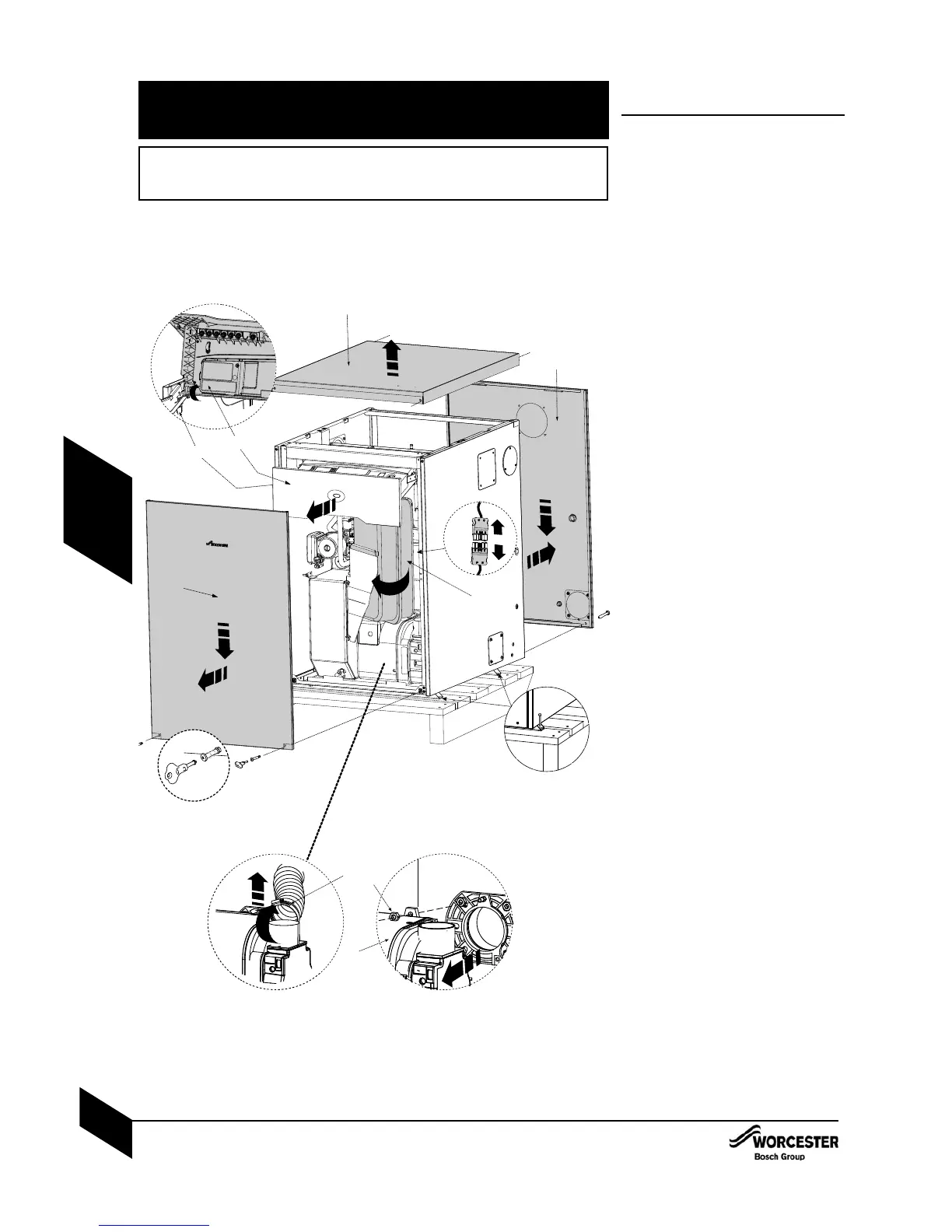
Note: The cabinet is not load bearing it
only provides weather protection for the
boiler inside.
14Mark position of the 100mm services
duct on the exterior wall and make a hole
through.
24Remove the screws securing the base
panel to the transit pallet and lift the boiler
off the pallet and into its installation
position taking care not to scrape the
base panel across the hard standing. Do
not attempt to lift and position the
boiler on your own. Do not use the
copper pipes to move the boiler.
4Fasten the base to the hard standing
using the holes provided. Care should be
taken to ensure that the base is level.
34Remove the screws (D) from each corner
of the top panel (E) and lift up to remove,
store safely away from the installation
point.
44Remove the key (A) for the door
fasteners from the literature pack.
Undo the screws at the bottom of
the front panel (B) using the key provided
and remove the screws from the rear
panel (C) - (optional) pulling both panels
down and out to remove. Store safely
away from the installation point.
54 Pull control box drawer (G) forward.
4 Depess the two levers (H), one on either
side beneath the slide rail, to release the
control box and pull fully forward.
4 Swivel the complete control box
assembly upwards.
64 Swivel the expansion vessel ( J ) on its
support bracket out of the boiler taking
care not to snag any electrical cables or
kink the flexible hose.
74Unplug the burner lead ( K ) from the
control box lead ( L ).
84Loosen the flexable air duct clamp (M)
and remove the air duct from the burner.
94Undo and remove the retainer (O) on top
of the burner. The burner (P) can now be
removed from the heat exchanger.
Store the burner and retainer nut safely
away from the boiler.
4Measure the 100mm Ø services duct
to give at least 10mm inside the casing
and to finish flush with the interior wall
surface, cut to size and fit the duct. Fit
the 100mm sealing ring where the duct
enters the casing and seal the joint to
the exterior wall and inside the cabinet
with a suitable sealant.
WARNING: THIS APPLIANCE IS SERVICED AND REPAIRED EXTERNALLY.
EXTERNAL EQUIPMENT OPERATED AT 230V SHOULD NOT BE INSTALLED, SERVICED OR
REPAIRED UNDER ADVERSE WEATHER CONDITIONS.
THIS APPLIANCE IS INSTALLED AND SERVICED EXTERNALLY TO THE PROPERTY, BUT
THE ENGINEER MUST HAVE ACCESS TO THE INSIDE OF THE PROPERTY WHEN
INSTALLING OR SERVICING THE APPLIANCE.
2
3
4
8
O
M
x4
3
A
B
C
D
D
D
E
P
G
5
6
7
L
K
9
J
H

 Loading...


