WEATHER COMPENSATION
The appliance will modulate the CH flow
temperature based on the outside temperature when
an outdoor sensor is connected to the outdoor
sensor connection on the control board and the
weather compensation is active.
This is designed for use with a system that has
thermostatic radiator valves and a room thermostat.
The appliance will operate at lower temperatures
when there is a lower heat load because the building
is losing less heat due to higher external tempera-
tures. This means that the appliance is running more
efficiently as it is operating for longer at condensing
temperatures.
The weather compensation curve can be adjusted to
tune the flow temperature to suit the particular
installation.
The appliance is supplied with the weather
compensation deactivated.
Weather compensation activation:
The weather compensation is activated via menu
1 of the text display.
4 Select Menu 1 via ▲ ▼ scroll buttons.
4 Press OK button.
4 Select W1 via ▲ ▼ scroll buttons.
4 Press OK button.
4 Set W1 to 1 via ▲ scroll button.
4 Press OK button.
The weather compensation is now active and the
appliance will check for the presence of an outdoor
sensor and deactivate the CH flow temperature
modulation if a sensor is not detected. When
weather compensation is activated but an outdoor
sensor is not fitted/detected, the warning triangle
and H03 will be displayed on the LCD display.
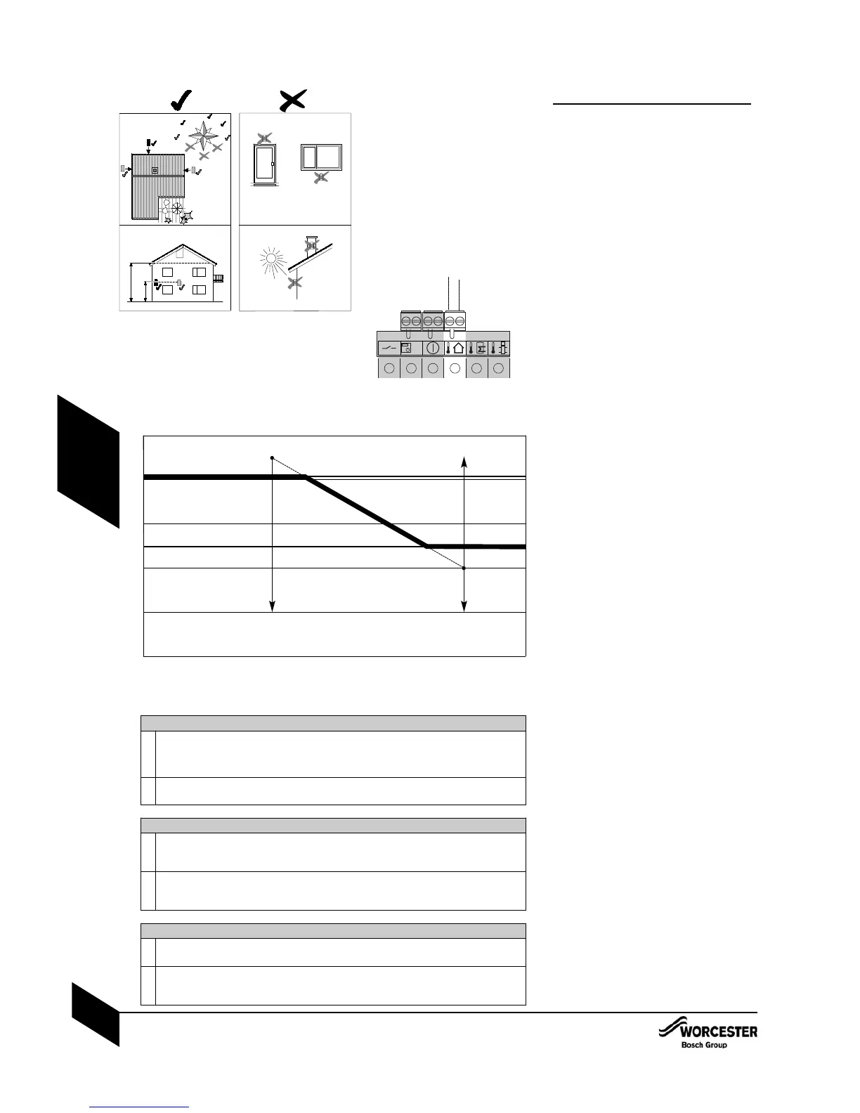
The heating curve:
The CH flow temperature has an upper limit of
82°C (this can be capped via the CH control
knob setting) and a lower limit of 50°C, (it is
recommended that the CH knob is set to 82°C
for the weather compensation to operate most
effectively).
The default settings for the curve are point A = 90°C
and point B = 40°C, this gives a 80°C flow at -4°C
outdoor temperature and a 50 °C flow at 14°C
outdoor temperature which should be suitable for
typical systems.
Point A is the projected value for the flow tempera-
ture at -10°C outdoor temperature and point B is the
projected value for the flow temperature at +20°C
outdoor temperature, (these values dictate the angle
of the slope only they are not CH flow temperature
limits).
Frost protection:
The normal condition for the appliance is that the
weather compensation frost protection is turned
Off.
If required the frost protection is activated via
Menu 1 W5 of the text display, 0 = OFF, 1 = ON.
On Activation of the weather compensation frost
protection if the outdoor temperature is less than
5°C the system frost protection is activated the
same as if an external frost thermostat was
activated.
100
80
60
40
20
-20 -10 0 10 20 30
0
-30
Minimum supply
Maximum supply setpoint
Heating curve
A
B
Average outdoor temperature
Supply temperature set point
Weather compensation heating curve
Adjusting the heating curve
l
The weather compensation curve can be adjusted via the text display by adjusting the
projected flow temperature at -10°C (point A), Menu 1 W2 (pA), and 20°C (point B),
W4 (pB), enabling the slope as well as the position of the curve to be adjusted to suit
the installation.
l
Point A and B can be set between 90 and 20°C but point A must always be greater than
point B.
Outdoor sensor error
l
If during weather compensation the outdoor sensor is open circuit or closed circuit the
CH flow temperature modulation is deactivated and the CH flow temperature set to the
CH control knob setting, a warning triangle and H03 are displayed on the LCD.
l
The appliance will monitor the outdoor sensor input and if the sensor returns to normal
then the flow temperature modulation will be reactivated and the LCD warning triangle
and H03 are turned Off, (there may be a 10 second delay).
Average outdoor temperature
l
To stop rapid fluctuations the outdoor temperature used for CH flow temperature
modulation is an average value taken over a ten minute period.
l
When an outdoor sensor is first detected the sensor value is taken to be the outdoor
temperature, subsequent to this the outdoor temperature will be adjusted every 10
minutes using an average outdoor temperature value from the previous 10 minute period.

 Loading...


