OIL BURNER & PUMP
INSTALLATION & SERVICING INSTRUCTIONS FOR GREENSTAR HEATSLAVE II EXTERNAL 12/18-18/25-25/32
6 720 805 210-01
28
INSTALLATION
CAUTION: ISOLATE THE OIL & WATER
MAINS SUPPLY BEFORE STARTING ANY
WORK AND OBSERVE ALL RELEVANT
SAFETY PRECAUTIONS.
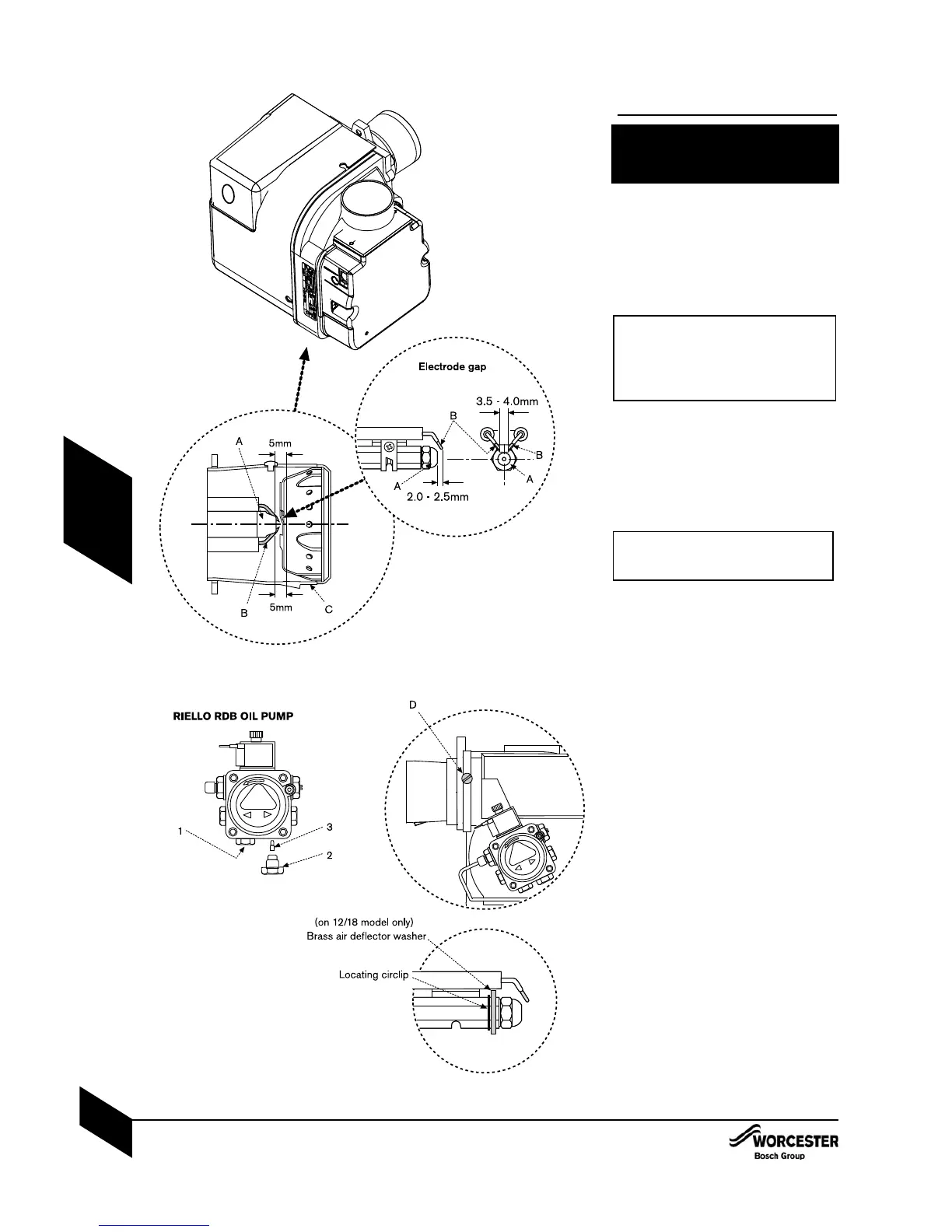
OIL BURNER:
14 Check the nozzle (A) and electrode (B)
settings are correct as shown opposite.
4 Ensure nozzle (A) is aligned centrally within
the combustion head (C).
4 Inspect for any visible defects.
2 IMPORTANT: Before removing or fitting a
nozzle (A), loosen screw (D) and move
the electrodes (B) forward.
After refitting check that the electrode
gaps are correct, as shown opposite.
NOTE: the 12/18 model has a brass deflection
washer and locating circlip behind the
nozzle. These must be in place for the
correct operation of the burner.
IMPORTANT: Whenever replacing the
combustion head, ensure that the
photocell is lined up with the sight hole.
OIL PUMP:
Connecting the oil pump for a single pipe
system:
4 The pump is factory set for single pipe
operation with the flexible oil pipe fitted.
4 Check connections before use.
Converting the oil pump for a double pipe
system:
14 Check the inlet pipe connection (1).
4 Unscrew return plug (2).
4 Screw in by-pass screw (3).
24 Connect the flexible oil pipe return hose
(not supplied) to the oil pump and return
pipe fixing (D on page 24) and tighten
to secure.
OIL BURNER & PUMP
1
2

 Loading...


