STARTING THE APPLIANCE
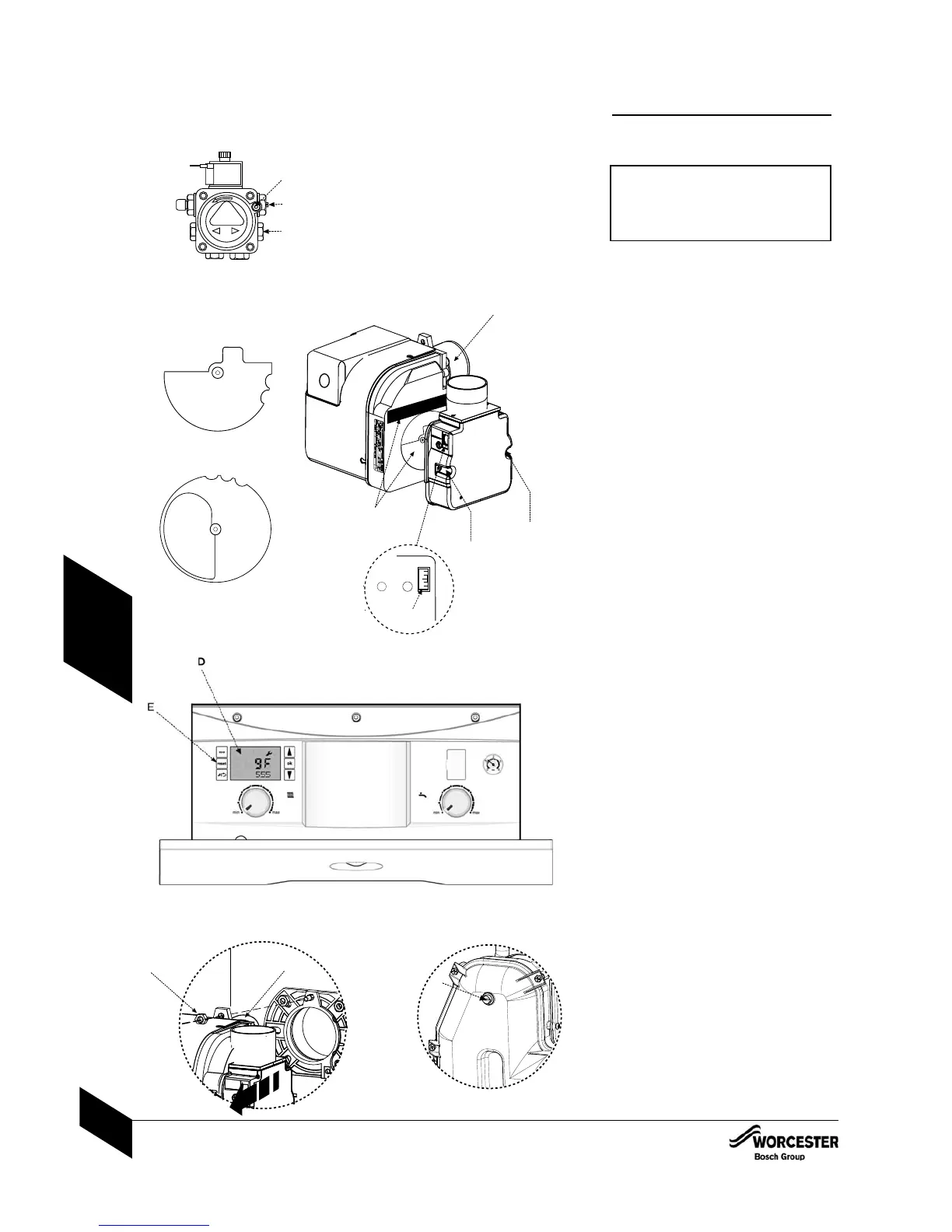
24 Fit a suitable pressure gauge to port (A) on
the oil pump.
IMPORTANT:
If changing the burner output, ensure the
position of the air damper disk is correct for
the desired output. Refer to the table on the
following page.
4 12/18 & 18/25 - RIELLO RDB 2.2
Adjust position of the air damper disc to suit
the burner output (see chart on page 44),
located as shown in the diagram opposite.
Access is by loosening the two star screws
(SC) to release the air inlet manifold.
• 25/32 - RIELLO RDB 2.2
No damper disk is fitted to the 25/32kW
burner.
4 Adjust the air shutter (L) and pump pressure
(B) as shown opposite. The burner should
ignite following a pre-ignition period of
approximately 15 seconds.
NOTE: The MO535 MRF control box has an
3.5 second delay before the start of
the pre-ignition.
Boiler lockout:
If the burner fails to establish a normal firing
pattern or flame failure occurs the flame
monitoring photocell mounted in the burner
body will alert the burner control box to shut the
burner down and provide a safe lockout state
indicated on the control panel LCD display (D)
by code 9F 555.
4Wait two minutes then press the lockout
reset button (E) to initiate another start
sequence.
4Repeat procedure until a flame is established.
34Start and run for 3 minutes then switch off.
4Check for after-spurting from the nozzle,
indicated by oil saturation on the combustion
head (G).
If after-spurting occurs:
4Release the burner retainer nut (H).
4Remove the burner, combustion head (G).
and electrodes, hold the burner vertical
to unscrew the nozzle and fill the nozzle
holder with oil.
4Refit nozzle, electrodes, combustion
head (G) and the burner.
4Restart and run for 3 minute intervals until
after-spurting stops.
44Start and run for 20 minutes.
4Remove sampling point plug ( J ) to check
the smoke reading is between 0-1. If the
smoke level is above 1, check the combustion
settings are correct and the oil nozzle is in
good condition.
NOTE: Smoke readings may be inaccurate until
the smoke from burning organic binder in
the access door insulation has ceased.
STARTING THE APPLIANCE
INSTALLATION & SERVICING INSTRUCTIONS FOR GREENSTAR HEATSLAVE II EXTERNAL 12/18-18/25-25/32
6 720 805 210-01
38
COMMISSIONING

 Loading...


