C-5000 Pilot’s Guide
Publication No. 150-041103 Page 40 of 51
Rev. C C-5000 Pilot’s Guide
Nov 2013
Appendix B – Mode 2 Operation
Overview
The C-5000 has the capability to control the RT-5000 in such a way that the user can monitor both the
main and the Guard (ITM) channel at the same time. This mode of operation is more difficult to use than
MODE 1.
The Home Page
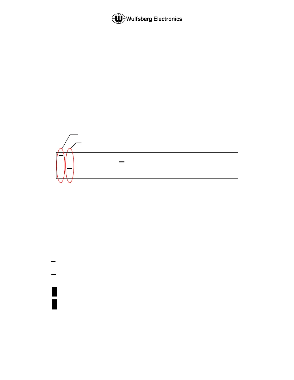
The only visible difference in the HOME PAGE from Mode 1 operation is in the Main/Guard status fields.
The illustration below depicts the HOME PAGE for a system comprised of two digital RT-5000 radios.
Both radios are configured to operate in Mode 2. The Main transceiver is the active transceiver on radio
1. The digital transceiver (Guard) is the active transceiver on radio 2. The active transceiver is the one
that will transmit when the push-to-talk switch is depressed.
1 1
1 2
A
W
1
2 2
. .
A
A
0 0 1
Main/Guard Status Fields – These fields display symbols indicating the current status of all the available
transceivers in the system. The symbols are as follows.
. – Indicates a radio is available, but not enabled.
► – Indicates a radio is transmitting.
1 – Indicates Main/Guard 1 is available and enabled, but not active.
2 – Indicates Main/Guard 2 is available and enabled, but not active.
1 – Indicates Main/Guard 1 is available, enabled, and active.
2 – Indicates Main/Guard 2 is available, enabled, and active.
1 – Indicates Main/Guard 1 is receiving.
2 – Indicates Main/Guard 2 is receiving.
Main Status Indicators
Guard Status Indicators
 Loading...