Basic Installation Procedures
14 Freedom X 2000 - 230V Owner's Guide
Step 1: Designing the Installation
Most Freedom X installations share common components, and
some of these are briefly described in Step 1: Designing the
Installation.
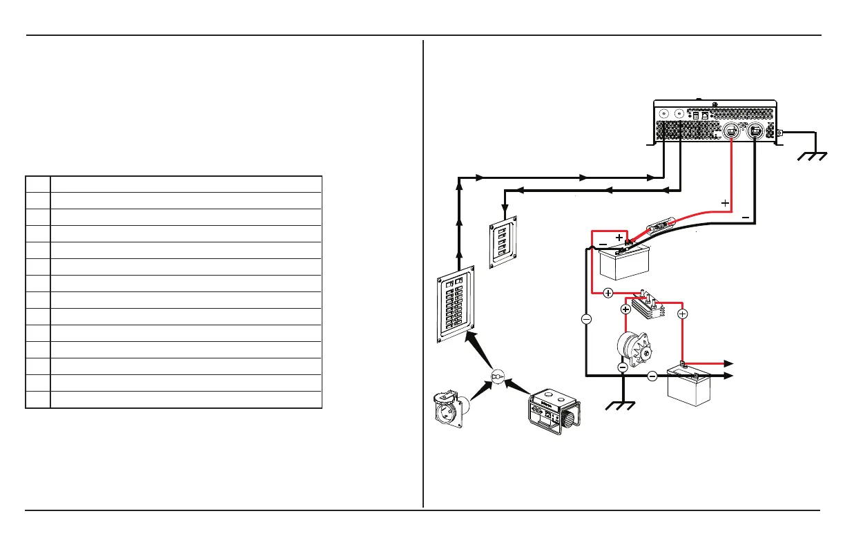
Figure 5 shows some components and their relationship to each
other in a typical recreational vehicle or fleet vehicle installation.
Also, see Marine Installation on page 39.
1 Equipment earth
2 Freedom X
3 DC fuse/disconnect/DC circuit breaker
4 12V deep cycle battery [house]
5 Battery isolator
6 Alternator
7 To engine
8 Equipment earth
9 Starting battery
10 AC load panel
11 AC source panel
12 Selector switch
13 Shore power
14 Generator
Figure 5 Typical Recreational Vehicle and Fleet Vehicle
Installation
 Loading...