Wiring Diagrams
7-12 11/06 FaxCentre 2121/2121L
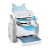
Electrical Components Layout
Figure 1
Table 1: Electrical Components Layout
Symbol Component Symbol Component
M1 Main Motor S2 Interlock
M2 Fuser Fan PE1 Paper Empty Sensor
H1 Fuser Heat Lamp PS3 Exit Sensor
TH1 Thermistor SL-1 Paper Feed Solenoid
TS1 Thermostat PU-1 LVPS
PH ROS HV-1 HVPS
S1 Paper Feed Switch PWB-P Main PWB

 Loading...