Page 8
TIPS fROm ThE PROS
PREPARING TO RUN YOUR RAIL bRUShLESS Off-ROAD bUGGY
n
Transmitter and Receiver
q Double-check that your transmitter is turned 'OFF'.
q Install the 'AA' Alkaline batteries into your transmitter, double-checking to make sure that the polarity (+/-) is correct. For more
information, refer to the separate radio control system Operating Manual included.
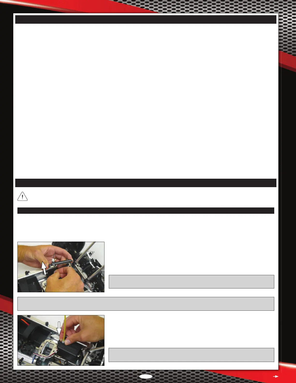
q Slide the receiver antenna wire into the antenna support tube.
q Loosen the knurled nut in the antenna mount, push the end of the antenna support
tube rmly down into the antenna mount, then tighten the knurled nut gently to lock
the antenna tube in place.
IMPORTANT: Leave any excess antenna wire hanging from the top of the antenna
support tube. Under no circumstances should you cut the antenna wire shorter.
PRO TIP: If you have difculty sliding the antenna wire through the antenna support tube in the next procedure, rst pull the antenna
wire through your ngers several times to straighten it, then lightly wet the antenna wire with glass cleaner.
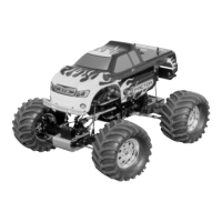
q Remove the four 3 x 10mm self-tapping screws that hold the receiver box lid in place,
then remove the receiver box lid.
q Uncoil the receiver antenna wire and feed it out through the hole in the receiver box
lid, then ret the receiver box lid, making sure not to pinch any of the wires.
IMPORTANT: Before reinstalling the receiver box lid, verify that the steering channel
and ESC throttle channel leads are plugged into channel 1 and channel 2, respectively.
Continued On Next Page
l
Separate instructions are included for the radio control system and the brushless Electronic Speed Controller/ESC programming card
included with your Rail Brushless Off-Road Buggy. Make sure to read both of them thoroughly, in addition to this Operating Manual,
before running your model for the rst time.
l
Double-check all of the fasteners to ensure that they're tight.
l
Do not overtighten any screws that thread into nylon or composite material, or the material may strip out. Screws threaded into nylon
or composite material need only be tightened snugly.
l
If you have difculty sliding the receiver antenna wire through the antenna support tube, rst pull the antenna wire through your ngers
several times to straighten it, then lightly wet the antenna wire with glass cleaner. The glass cleaner will make the antenna wire slide
through the support tube much easier. Leave any excess antenna wire hanging from the top of the antenna support tube. Under no
circumstances should you cut the antenna wire shorter.
l
In some cases, if the battery retaining straps are left too long, they can interfere with the correct t of the body shell. If this occurs,
cut away the excess material from the battery retaining straps prior to installing the body shell.
l
The ESC battery leads feature male battery connectors on both the positive and the negative leads. This allows plug-and-play
compatibility with most hard-case Li-Po car battery packs and allows easy dual battery pack wiring with the use of one simple jumper.
If you prefer to change the connectors, make sure to observe correct polarity and use heat-shrink tubing to insulate the solder joints.
l
Before checking the steering and throttle controls, we recommend placing the Rail on a car stand so that the wheels are off the ground.
This will ensure your safety and the safety of your model while testing the throttle control.
l
If the motor does not seem to be producing full power, double-check that your batteries are fully charged, then double-check that your
transmitter's throttle channel EPA is set to 100%.
l
Before making programming changes to the ESC using the ESC programming card, remove the pinion gear from the motor. This will
ensure your safety and prevent any chance of a runaway model.
l
If you drive your Rail in sand, we strongly recommend using the optional foam lter over the motor heat-sink fans to keep sand out
of the fans. For more information, see the Option Parts List on page 67.
For clarity, the photographs in this section show the roll cage pulled up pivoted forward. While not necessary to complete these
steps, doing this makes it easier to access the chassis components. For more information, see page 20.