To adjust the gib for excessive clearance: Loosen the gib lock screw on the back of
the saddle. Estimate the amount of gib lock screw adjustment required, and tighten the
gib lock screw on the front of the saddle. Tighten the gib lock screw on the back end of
the saddle to lock the gib in place, and recheck. Repeat as necessary.
To adjust the gib for too small of a clearance: Loosen the gib lock screw on the
front of the saddle. Estimate the amount of gib lock screw adjustment required and
tighten the gib lock screw on the back of the saddle. Tighten the gib lock screw on the
front of the saddle to lock the gib in place, and recheck. Repeat as necessary.
5.2.1.6
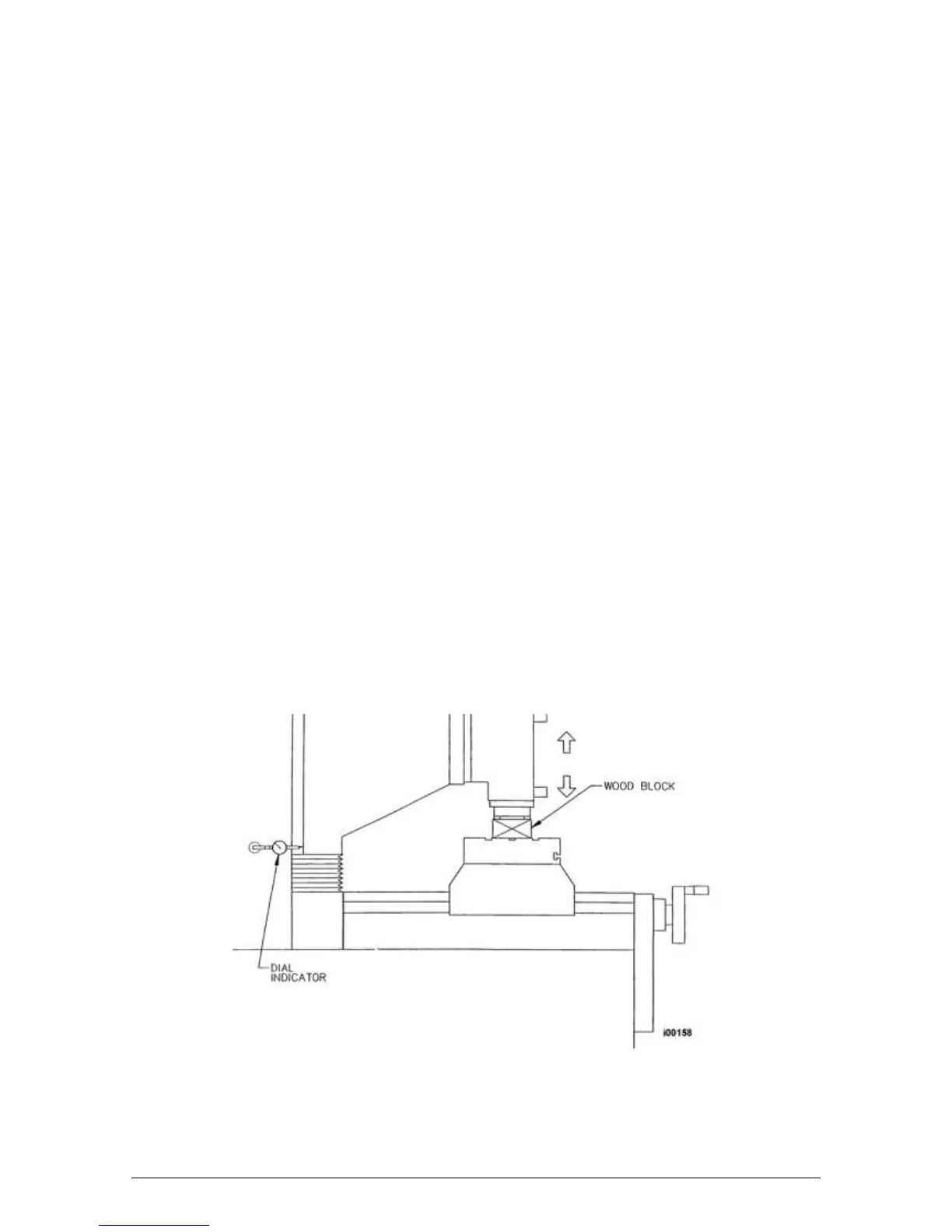
Head Back Gib Adjustment - Z Axis
1. Clean all swarf, dirt and excess oil from the table and saddle.
2. Disconnect one end of the upper and lower way cover where it is attached to the ram.
3. Position the milling head such that the table can be reached by extending the quill
approximately 3/4 of its travel.
4. Place a wood block on the table underneath the spindle.
5. Attach a dial indicator with a magnetic base to the column near the base of the ram on the
left side of the machine. Place the indicator stylus on the rear surface of the ram near the
bottom.
6. Extend the quill until it touches the wood block. Using the quill handle, push the spindle nose
against the wood block and note the amount of movement on the dial indicator. Adjust the
left side gib until the registered movement is 0.02-0.01mm.
To adjust the gib for excessive clearance: Loosen the gib lock screw on the bottom
of the ram. Estimate the amount of gib lock screw adjustment required and tighten the
gib lock screw on the top of the ram. Tighten the gib lock screw on the bottom of the
ram to lock the gib in place, and recheck. Repeat as necessary.
To adjust the gib for too small of a clearance: Loosen the gib lock screw on the top
of the ram. Estimate the amount of gib lock screw adjustment required and tighten the
gib lock screw on the bottom of the ram. Tighten the gib lock screw on the bottom of the
ram. Tighten the gib lock screw on the top of the ram to lock the gib in place, and
recheck. Repeat as necessary.
7. Run Service Code 12 to set the feed forward constant.
8. Repeat the procedure for the back gib on the right side of the machine.
Figure 41 - Head Back Gib
 Loading...