CYLINDER AND PISTON
5-25
EAS24380
REMOVING THE PISTON
1. Remove:
● Piston pin clips “1”
● Piston pin “2”
● Piston “3”
CAUTION:
ECA13810
Do not use a hammer to drive the piston pin
out.
NOTE:
● Before removing the piston pin clip, cover the
crankcase opening with a clean rag to prevent
the piston pin clip from falling into the crank-
case.
● Before removing the piston pin, deburr the pis-
ton pin clip's groove and the piston's pin bore
area.
2. Remove:
● Top ring
● 2nd ring
● Oil ring
NOTE:
When removing a piston ring, open the end gap
with your fingers and lift the other side of the ring
over the piston crown.
EAS24400
CHECKING THE CYLINDER AND PISTON
1. Check:
● Piston wall
● Cylinder wall
Vertical scratches → Rebore or replace the
cylinder, and replace the piston and piston
rings as a set.
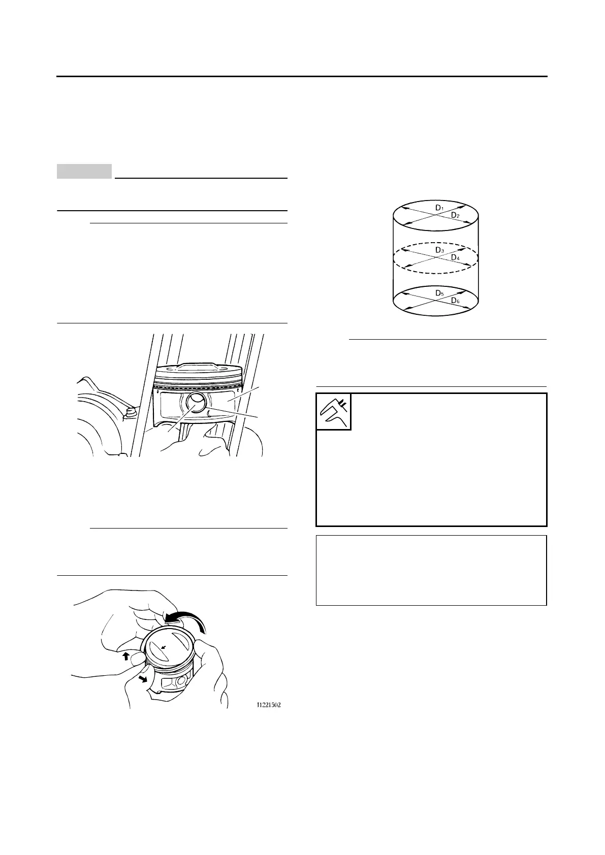
2. Measure:
● Piston-to-cylinder clearance
▼▼▼▼▼▼▼▼▼▼▼▼▼▼▼▼▼▼▼▼▼▼▼▼▼▼▼▼▼▼▼▼
a. Measure cylinder bore “C” with the cylinder
bore gauge.
NOTE:
Measure cylinder bore “C” by taking side-to-side
and front-to-back measurements of the cylinder.
Then, find the average of the measurements.
b. If out of specification, replace the cylinder,
and the piston and piston rings as a set.
c. Measure piston skirt diameter “D” with the mi-
crometer.
2
1
3
Cylinder bore “C” -
Bore
79.000–79.010 mm
(3.1102–3.1106 in)
Taper limit
0.05 mm (0.0020 in)
Out of round limit
0.100 mm (0.0039 in)
Warp limit
0.03 mm (0.0012 in)
“C”=maximum of D1–D6
“T”=maximum of D1 or D2—maximum of D5
or D6
“R”=maximum of D1, D3 or D5—minimum of
D2, D4 or D6
 Loading...