7 - 30
FI
THROTTLE BODY
NOTE:
Check mainly that the resistance changes
gradually when turning the throttle, since the
readings (from closed to wide-open throttle)
may differ slightly from those specified.
▲▲▲▲ ▲ ▲▲▲▲ ▲ ▲▲▲▲ ▲ ▲▲▲▲ ▲ ▲▲▲▲ ▲ ▲▲▲▲ ▲▲▲
Throttle position sensor resis-
tance
(0.52 ~ 0.9) ~ (4.0 ~ 6.0) k
Ω
at 20 °C (68 °F)
(yellow – black/blue)
2. Adjust:
• throttle position sensor angle
▼▼▼▼ ▼ ▼▼▼▼ ▼ ▼▼▼▼ ▼ ▼▼▼▼ ▼ ▼▼▼▼ ▼ ▼▼▼▼ ▼▼▼
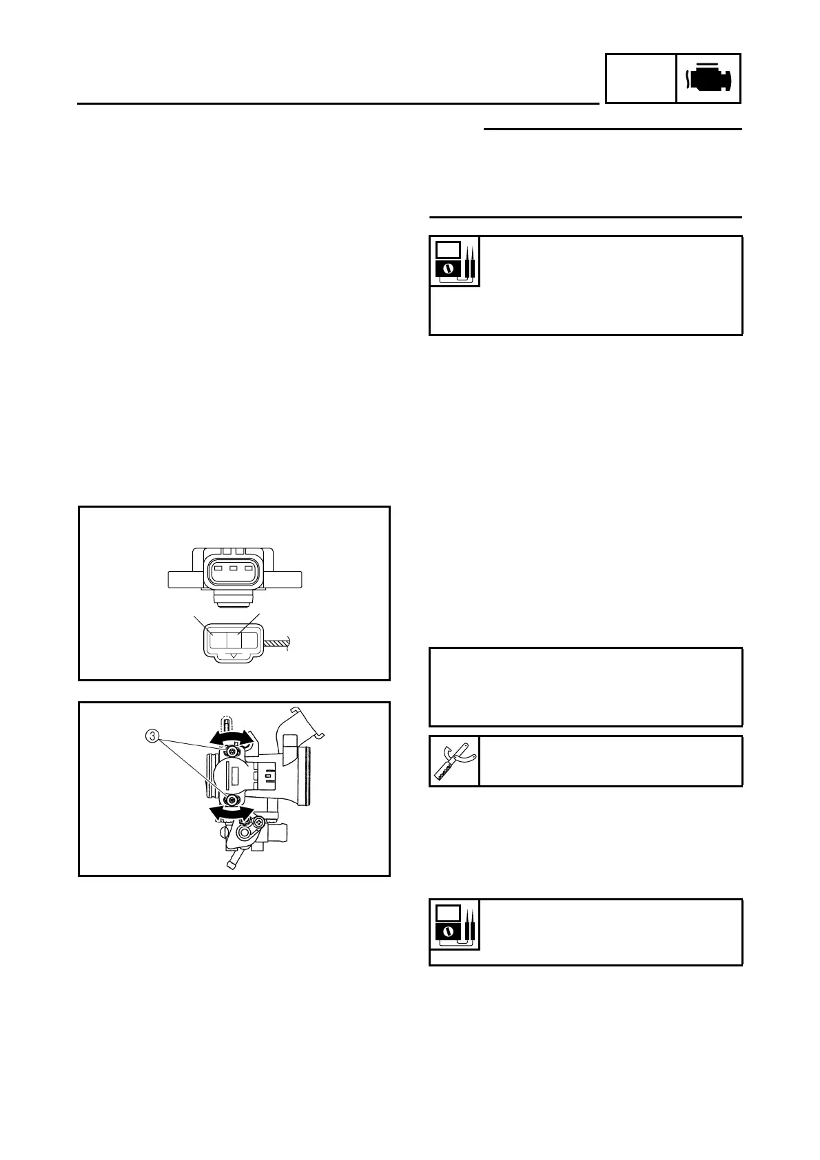
a. Connect the throttle position sensor coupler
to the wire harness.
b. Connect the digital circuit tester to the throt-
tle position sensor.
c. Measure the throttle position sensor volt-
age.
d. Adjust the throttle position sensor angle so
that the voltage is within the specified
range.
e. After adjusting the throttle position sensor
angle, tighten the throttle position sensor
screws 3.
▲▲▲▲ ▲ ▲▲▲▲ ▲ ▲▲▲▲ ▲ ▲▲▲▲ ▲ ▲▲▲▲ ▲ ▲▲▲▲ ▲▲▲
Positive tester probe
→
yellow terminal
1
Negative tester probe
→
black/blue terminal
2
Digital circuit tester
90890-03174
Throttle position sensor voltage
0.63 ~ 0.73 V
(yellow – black/blue)
1
L
Y
B/L
2








 To Next Page