8 - 12
– +
ELEC
IGNITION SYSTEM
EAS00746
YES
NO
EAS00748
YES
NO
EAS00749
YES
NO
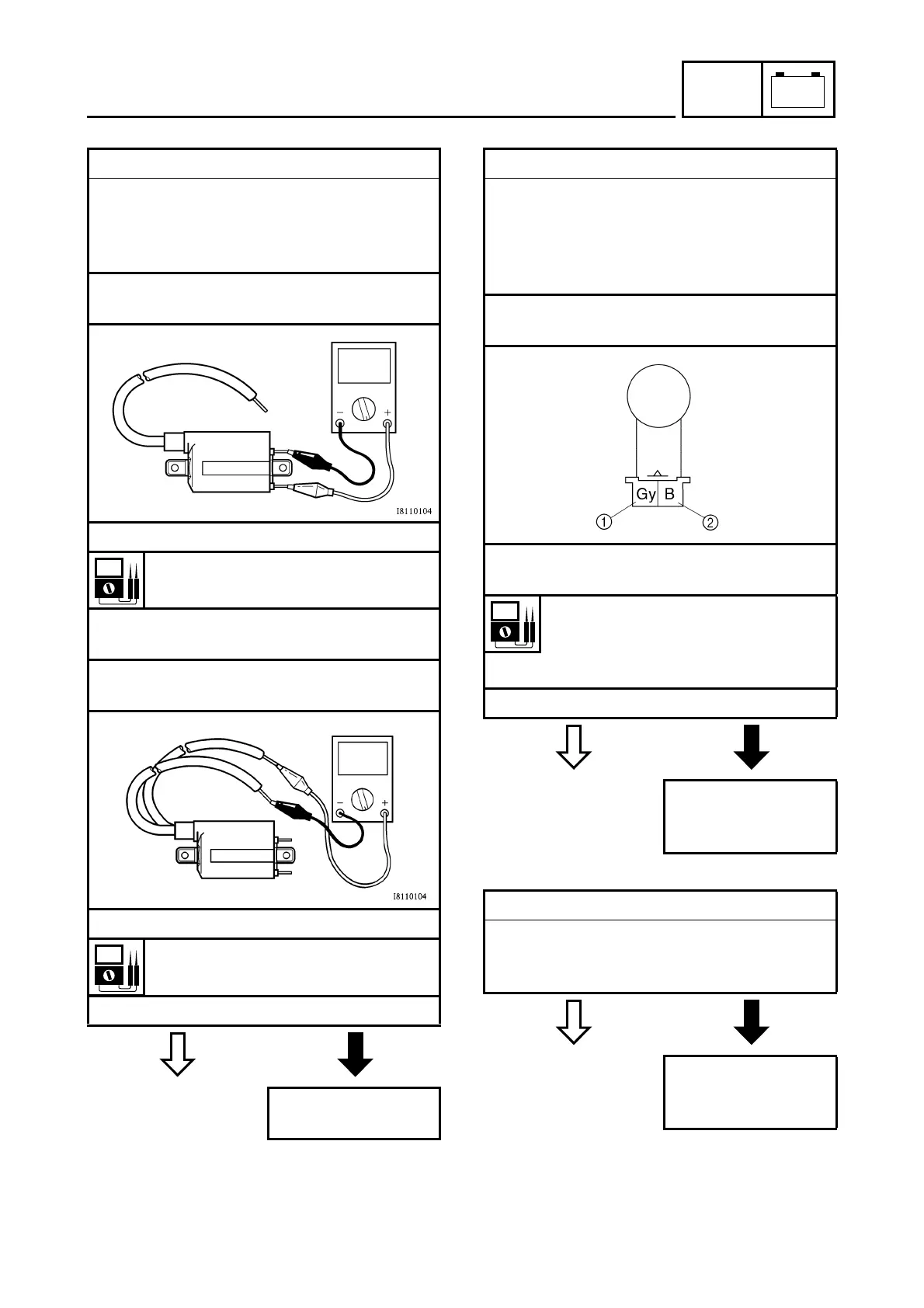
6. Ignition coil resistance
• Disconnect the ignition coil connectors
from the ignition coil terminals.
• Connect the pocket tester (
Ω
×
1) to the
ignition coil as shown.
Positive tester probe
→
red/black
Negative tester probe
→
orange
• Measure the primary coil resistance.
Primary coil resistance
1.87 ~ 2.53
Ω
at 20 °C (68 °F)
• Connect the pocket tester (
Ω
×
1k) to the
ignition coil as shown.
Negative tester probe
→
spark plug lead
1
Positive tester probe
→
spark plug lead
2
• Measure the secondary coil resistance.
Secondary coil resistance
12 ~ 18 k
Ω
at 20 °C (68 °F)
• Is the ignition coil OK?
Replace the ignition
coil.
7. Crankshaft position sensor resistance
• Disconnect the crankshaft position sensor
coupler from the wire harness.
• Connect the pocket tester (
Ω
×
100) to the
crankshaft position sensor terminal as
shown.
Positive tester probe
→
gray
1
Negative tester probe
→
black
2
• Measure the crankshaft position sensor
resistance.
Crankshaft position sensor resis-
tance
189 ~ 231
Ω
at 20 °C (68 °F)
(between gray and black)
• Is the crankshaft position sensor OK?
Replace the crank-
shaft position sensor/
stator assembly.
8. Main switch
• Check the main switch for continuity.
Refer to “CHECKING THE SWITCHES”.
• Is the main switch OK?
Replace the main
switch/immobilizer
unit.











 To Next Page